


0 引言
当前人类社会面临的能源危机日益严峻,可控核聚变具有储量大、安全性高、对环境友好的特点,是未来最有可能从根本上解决能源危机的能量获取方式[1]。
作为该预研装置核心部件之一的磁压缩磁体,具有直径超800 mm、磁感应强度超7 T、磁场上升时间小于500 μs的特点。目前该类型磁体部分应用于直线型聚变装置,如美国洛斯阿拉莫斯国家实验室建造的Field-Reversed Experiment-C(FRX-C)装置[6],其压缩区长3 m,半径0.23 m,压缩线圈可在55 μs内将压缩区的磁感应强度从0.4 T提升至1.8 T[7];日本大阪大学建造的FRC Injection Experiment(FIX)装置[8],其压缩区长5 m,半径0.4 m,压缩线圈可在35 μs内将压缩区磁感应强度从0.04 T提升至1.5 T[9];华中科技大学建造的磁压缩场反等离子体HUST-FRC(HFRC)装置[10],其压缩区长3 m,半径0.4 m,压缩线圈可在50 μs内将压缩区磁感应强度从0.1 T提升至1.2 T[11]。由此可见,以上装置的磁场较小,磁体结构设计无法直接作为本磁体的设计参考。应用于托卡马克装置的中心螺线管线圈(central solenoid,CS),如:中国聚变工程实验堆(China fusion engineering test reactor,CFETR)的CS线圈[12],其磁场区域长12.8 m,半径为1.75 m,最大稳态磁感应强度为12 T[13];国际热核聚变实验堆(international thermonuclear experiment reactor,ITER)的CS线圈,其磁场区域长度13 m,半径2 m,最大稳态磁感应强度达13 T[14]。由于CS线圈在设计阶段进行结构仿真分析时,该装置的激励设置通常为直流稳态[15],且本磁体装置的磁场在达到峰值时没有稳态持续时间,因此本磁体在设计阶段不能忽视磁场变化率对磁体受力产生的影响。本磁体装置需要结合以上各类磁体的设计优点,达成直径超800 mm、磁感应强度超7 T、磁场上升时间小于500 μs的设计目标。
本文以磁压缩磁体对磁场的设计要求为目标,利用有限元分析软件建立磁压缩磁体初步设计方案的二维电磁-结构仿真模型,探究导体材料选取、线圈组导体匝间间距以及导体径向厚度对导体最大等效应力的影响,在满足设计要求的前提下,兼顾建造成本,构建一套针对磁压缩磁体导体部分的设计思路,为后续对完整的磁压缩磁体结构设计做好铺垫。
1 磁体初步设计方案
图1
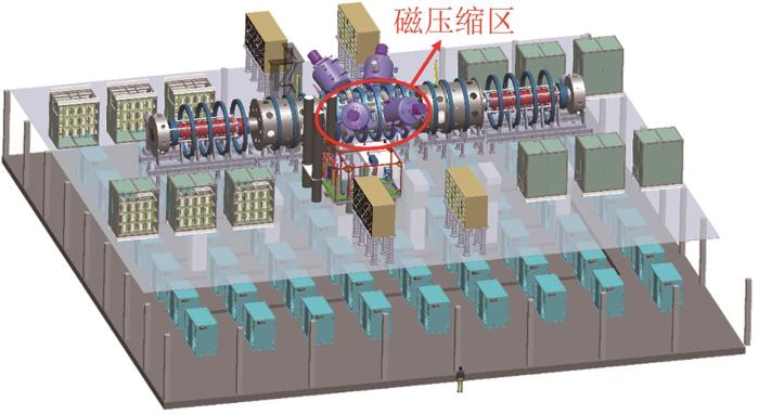
图1
磁约束氘-氘聚变中子源预研装置示意图
Fig. 1
Schematic diagram of the preliminary research device of magnetic confinement deuterium-deuterium fusion neutron source
图2
图3
图4
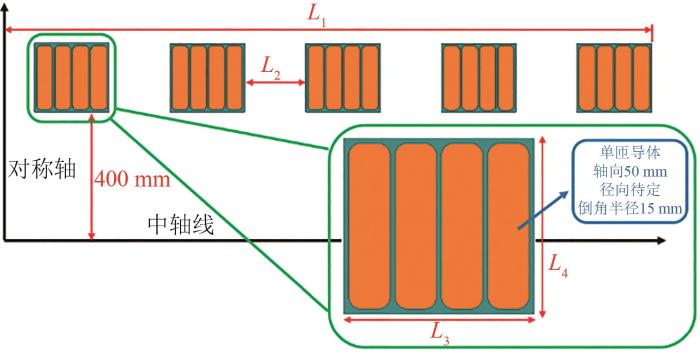
表1 长度的具体参数
Tab. 1
| 参数 | 长度/mm | ||||
|---|---|---|---|---|---|
| L1 | L2 | L3 | L4 | ||
| 匝间距/mm | 6 | 2 000 | 189 | 230 | 212 |
| 10 | 2 000 | 167 | 250 | 220 | |
| 14 | 2 000 | 145 | 270 | 228 | |
| 径向厚度/mm | 150 | 2 000 | 145 | 270 | 178 |
| 175 | 2 000 | 145 | 270 | 203 | |
| 200 | 2 000 | 145 | 270 | 228 | |
2 仿真研究
2.1 仿真参数设置
表2 导体材料电气参数
Tab. 2
| 材料 | 相对介电常数 | 相对磁导率 | 体积电导率 |
|---|---|---|---|
| 纯铜 | 1 | 0.999 991 | 58 |
| B30白铜 | 1 | 1.03 | 4.7 |
结构仿真中各材料的结构参数见表3。导体与绝缘层之间的接触面类型设置为绑定接触,线圈组轴向两边的约束条件设置为仅压缩支撑,径向边界不予约束。设置好网格划分以后,将电磁分析中计算得到的最大力密度电磁载荷导入结构仿真模块中进行线圈组应力的计算。
表3 线圈组材料结构参数
Tab. 3
| 材料 | 杨氏模量/GPa | 泊松比 | 许用应力/MPa |
|---|---|---|---|
| 纯铜 | 120 | 0.343 | 70 |
| B30白铜 | 150 | 0.32 | 200 |
| 环氧树脂 | 24 | 0.13 | 250 |
2.2 导体材料对应力的影响
因磁场在达到峰值之前的变化率与500 Hz频率的前1/4正弦波的变化率相似,如此快速变化的电流会导致电流集中在各匝线圈的内表面,这种现象称为趋肤效应,趋肤深度δ表达式为
式中:f为工作频率;μ为导体的磁导率。由表2数据计算可知,导体材料设置为B30白铜时,其趋肤深度约为纯铜导体趋肤深度的3.5倍。
图5
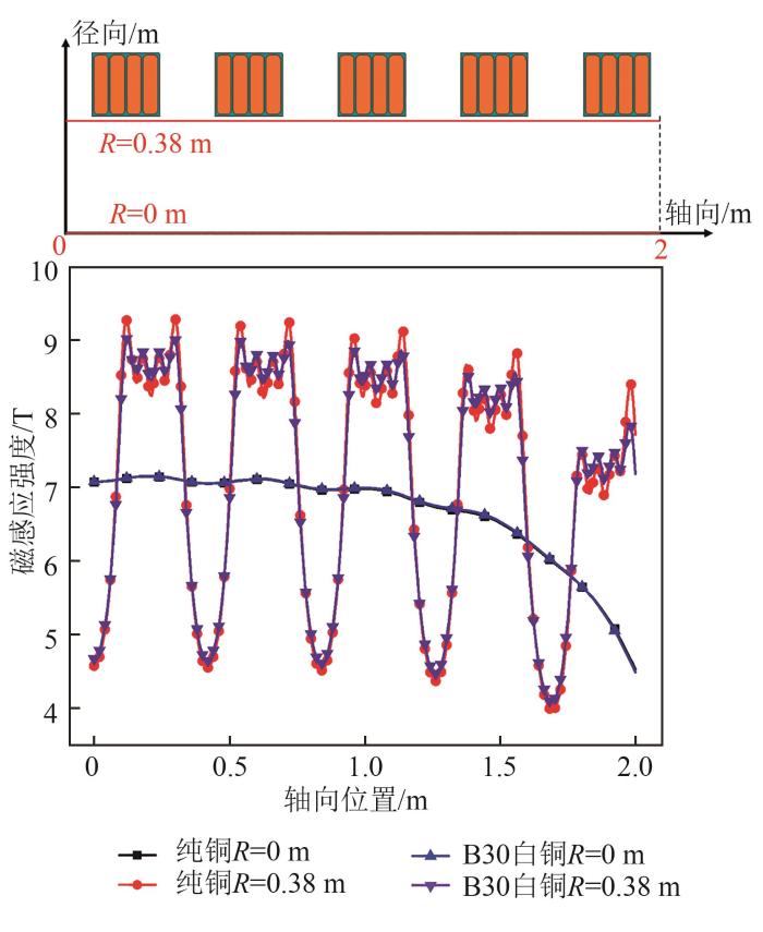
图5
不同导体材料各径向位置的磁感应强度曲线图
Fig. 5
Curves of magnetic induction intensity at each radial position of different conductor materials
图6
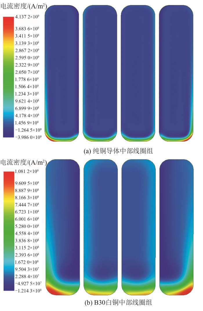
图6
不同导体材料峰值电流密度云图
Fig. 6
Peak current density cloud map of different conductor materials
由图5可知,中部线圈组所处位置的磁感应强度大于端部线圈组,由此可以判断出后续设计应该主要围绕中部线圈组进行。通过仿真也验证了这一判断,以纯铜为导体材料,计算出中部线圈组最大等效应力为200 MPa,端部线圈组最大等效应力为145 MPa。
图7
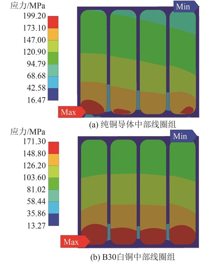
图7
不同导体材料线圈组等效应力云图
Fig. 7
Equivalent stress nephogram of coil groups with different conductor materials
综上,无论是从电流均匀性还是许用应力的角度来看,纯铜无法作为本磁体装置的导体材料,B30白铜有望成为备选材料,且导体最大应力会随电流均匀性提高而降低。但过低的电导率材料会造成更大的欧姆损耗与发热情况,因此在最终确定导体材料之前还应对相关情况进行论证。
2.3 导体匝间距对应力的影响
图8
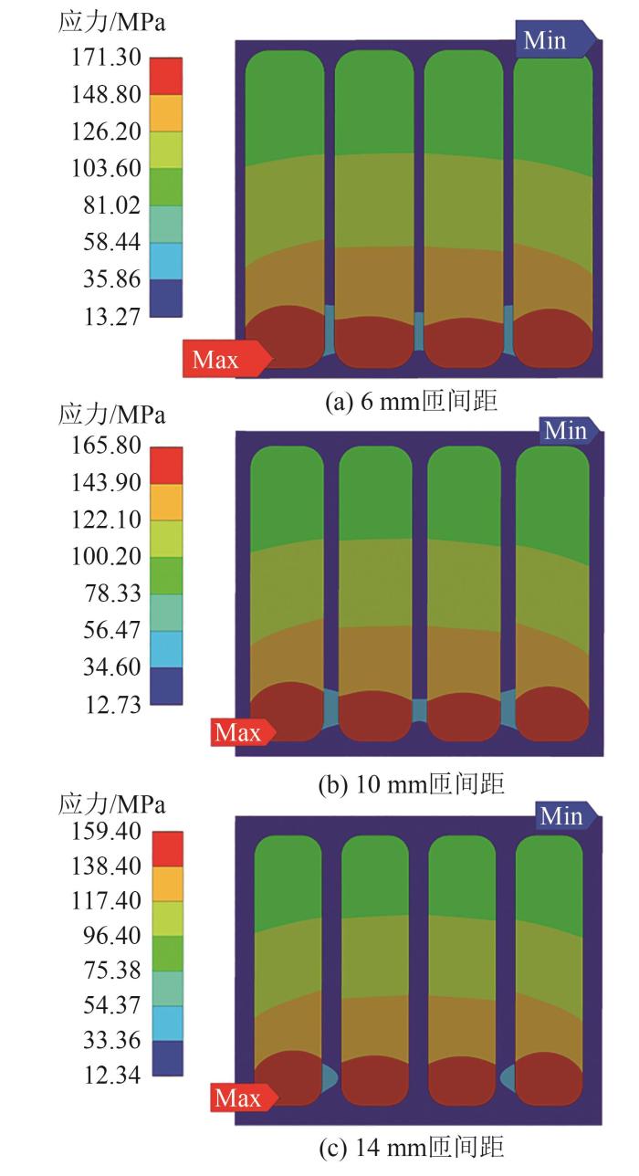
图8
不同匝间距线圈组等效应力云图
Fig. 8
Equivalent stress nephogram of coil group with different turn spacing
图9
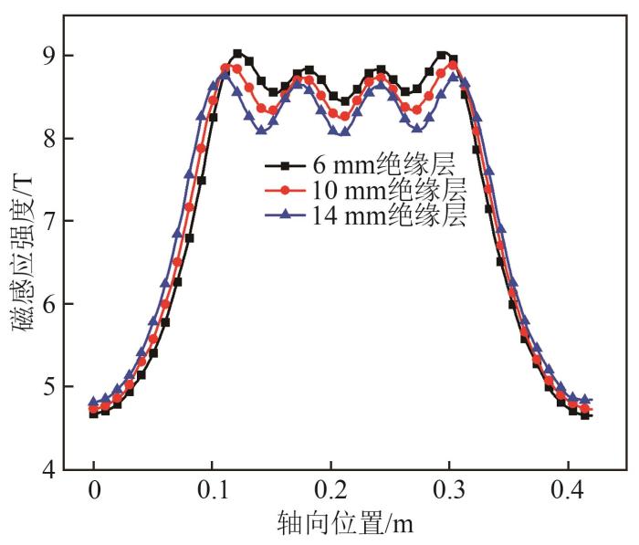
图9
不同绝缘层厚度下磁感应强度曲线图
Fig. 9
Curve of magnetic induction intensity under different insulating thicknesses
由图9可以看出,随着匝间距的增加,导体附近各轴向位置下的磁感应强度均有明显下降,由此使得导体的最大等效应力降低。因此在后续磁体设计中,导体的匝间距可以考虑在允许的范围内适当增加。
2.4 导体径向厚度对应力的影响
图10
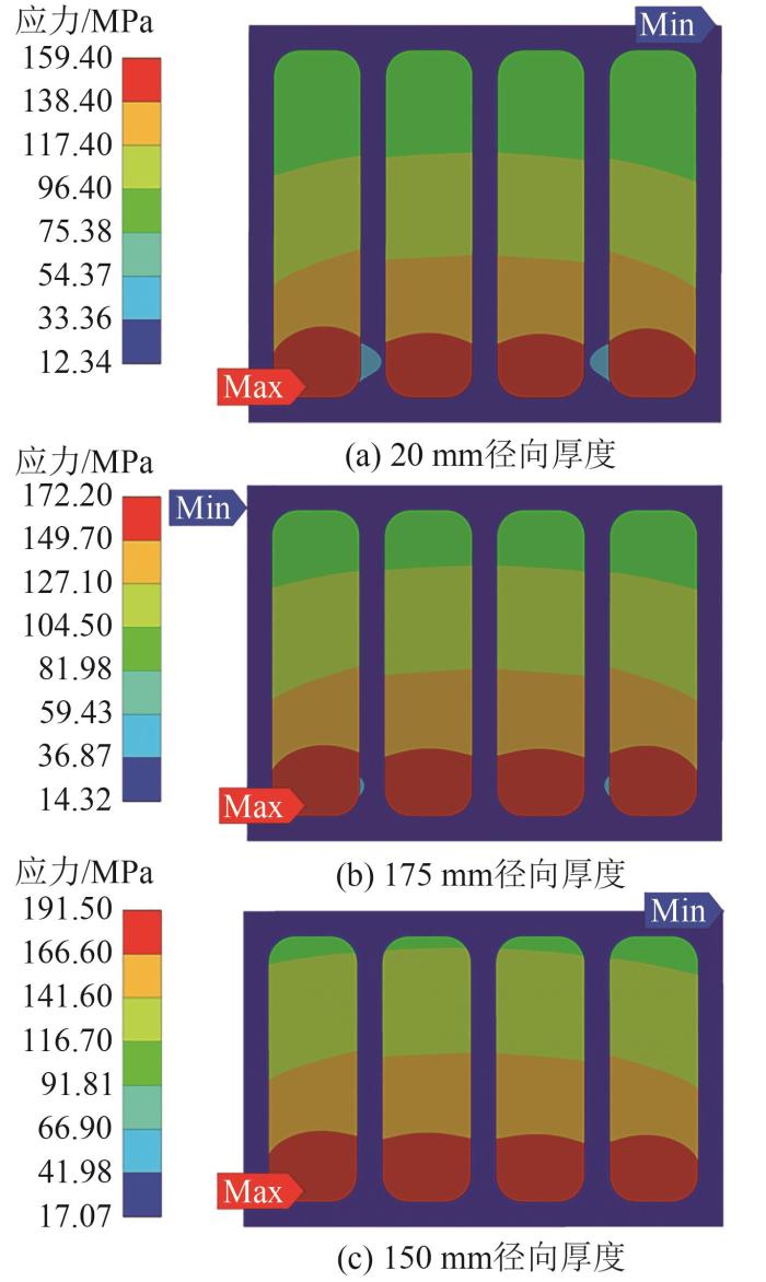
图10
不同径向厚度的线圈组等效应力云图
Fig. 10
Equivalent stress nephogram of coil groups with different radial thicknesses
由图10可知,在导体材料选用B30白铜,匝间距14 mm时,径向厚度若取为150 mm,导体的最大应力已经接近B30白铜的许用应力200 MPa。
为进一步探究造成线圈组最大等效应力发生变化的原因,分别对各径向厚度线圈组的各法向应力进行分析,各法向应力最大值见表4。
表4 不同径向厚度的线圈组各法向应力最大值
Tab. 4
| 径向厚度/mm | 等效应力/MPa | 径向应力/MPa | 轴向应力/MPa | 环向应力/MPa |
|---|---|---|---|---|
| 150 | 191.47 | -57.80 | -49.58 | 173.41 |
| 175 | 172.21 | -58.89 | -49.99 | 154.31 |
| 200 | 159.44 | -59.61 | -50.23 | 140.12 |
由表4可见,不同径向厚度下中部线圈组导体之间的最大径向应力与轴向应力相差无几,随着径向厚度由200 mm减少至150 mm,环向应力由140.12 MPa增加至173.41 MPa,这是由于中部线圈组呈现出两端向中间挤压、整体向外膨胀的趋势,而减少导体径向厚度对电磁力的影响不大,但线圈组向外膨胀的趋势愈发明显,这会导致导体在环向上的应变增加,进而环向应力增加。
3 结论
利用有限元仿真软件进行电磁-结构相耦合的有限元仿真,从导体材料、导体匝间距以及导体径向厚度3方面入手,得出以下结论:
1)低电导率的材料会对导体趋肤效应有所改善,可以使导体截面电流密度的均匀性得到提升,当导体材料电导率从58 MS/m降至7.4 MS/m时,导体最大等效应力从200 MPa降至171 MPa,降幅14.3%。
2)适当增加导体匝间距可以降低导体内表面附近的磁感应强度,当匝间距离由6 mm增加至14 mm时,导体最大等效应力从171 MPa降至160 MPa,降幅6.4%。
3)减小导体径向厚度对导体环向应力的增加最为显著,为降低建设成本,可在导体材料的许用应力的范围内适当减小导体的径向厚度。
参考文献
ITER计划和核聚变研究的未来
[J].
Iter program and the future of nuclear fusion research
[J].
Helium-hydrogen synergistic effects in structural materials under fusion neutron irradiation
[J].
Scoping of material response under DEMO neutron irradiation:comparison with fission and influence of nuclear library selection
[J].
基于场反位形的磁约束氘氘脉冲聚变中子源方案设计
[J].
Project design of a pulsed D-D fusion neutron source based on field reversed configuration
[J].
A new device concept of magnetic confinement deuterium-deuterium fusion
[J].
High-power magnetic-compression heating of field-reversed configurations
[J].
Review of the Los-Alamos FRX-C experiment
[J].
Field reversed configurations
[J].
Advanced experiments on field-reversed configuration at Osaka
[J].
HFRC磁压缩场反等离子体装置的压缩区设计
[D].
Compression region design of HFRC magnetic compression field anti-plasma device
[D].
Structural optimization design and numerical analysis of in-vessel magnetic compression coils
[J].
CFETR模型线圈引线的力学分析
[J].
Mechanical analysis of feeder for CFETR CS model coil
[J].
CFETR中心螺线管线圈结构设计和电磁分析
[D].
Structural design and electromagnetic analysis of CFETR central solenoid coil
[D].
ITER central solenoid precompression test mock-up-validation phase to prepare the assembly on-site
[J].
CFETR中心螺线管模型线圈结构
[D].
CFETR center solenoid model coil structure
[D].
Optimization of the pulsed high-field coil in a magnetic trap type plasma compression device
[J].
