0 引言
燃煤发电是电力供应的主要形式,国际能源署( International Energy Agency,IEA)在《2021年煤炭报告》中称,2021年电力需求增长超过了低碳能源供给能力,导致燃煤发电厂的发电量猛增9%[1 ] 。在经历2021年的能源短缺危机后,煤炭等传统能源在现阶段的能源系统中仍占据主导地位。然而,煤炭作为全球电力发展的基石,发展节能减排技术至关重要[2 -3 ] 。
节能减排作为我国火力发电行业的研究热点,目前研究主要集中在降低热端不可逆损失、减少系统内部不可逆损失及降低冷端不可逆损失3个方面[4 ] 。在降低热端不可逆损失的研究中,以提高主蒸汽和再热蒸汽参数作为优化的主要手段,高参数超超临界燃煤发电技术能够有效提升机组效率,并且减少温室气体的排放[5 -8 ] 。但是,由于耐高温材料阻碍高参数超超临界燃煤发电技术的发展[9 ] ,目前的主蒸汽温度最高为605 ℃,再热蒸汽温度最高达到620 ℃[10 ] 。机组的冷端受限于地理条件,这部分不可逆损失的研究主要集中于冷端构型设计[11 ] 。
除了通过提高热端参数和降低冷端参数来提升机组效率,还可以通过调整机组的三维结构[12 ] 来提升机组的经济性。采用汽轮机高位布置技术能大幅减少耐高温管道的使用,从而提升机组的经济性[13 -15 ] 。虽然目前汽轮机高位布置技术已经成熟[16 -17 ] ,但是现有研究大多从热力学第一定律的角度进行分析[18 -20 ] ,鲜少对采用汽轮机高位布置技术的机组不可逆性进行分析。
通过㶲分析可以评估系统的不可逆性分布,为系统优化提供参考[21 ] 。采用汽轮机高位布置的燃煤机组热力性能变化规律与常规布置机组相似[22 ] ,但是就投资成本而言,采用汽轮机高位布置的燃煤机组土建结构投资成本比常规布置机组成本高。因此,有必要对采用汽轮机高位布置的燃煤机组的㶲经济性变化规律进行研究。
为此,本文建立采用汽轮机高位布置技术的燃煤机组的㶲模型和㶲经济性模型,分析机组变工况下的流股、设备㶲效率变化以及成本变化,为后续机组的优化研究提供参考。
1 汽轮机高位布置技术的㶲和㶲经济性分析模型
汽轮机系统由回热加热器、凝汽器、汽轮机本体等设备构成,基于热力学第二定律建立机组的㶲模型,统筹汽轮机高位布置技术的实际运行情况,建立㶲经济性分析模型。
1.1 㶲分析模型
物质的㶲表示该物质所具有的最大能量,㶲分析从能量的数量和质量2个方面揭示出装置或设备在能量中㶲的传递、转换、利用和损失情况,从而分析系统损失的原因、部位,进而提出改进方向。
假定㶲分析的环境参数如下:压力p 0 =0.1 MPa,温度T 0 =298.15 K。燃煤发电机组以水为介质,单位质量水的㶲计算公式[23 -24 ] 如下:
e x = ( h - h 0 ) - T 0 ( s - s 0 ) (1)
式中:h 为单位质量水的焓值,kJ/kg;h 0 为环境条件下单位质量水的焓值,kJ/kg;s 为单位质量水的熵值,kJ/(kg⋅K);s 0 为环境条件下单位质量水的熵值,kJ/(kg⋅K)。
燃煤发电机组以煤为载体,单位质量煤的㶲计算公式如下:
e c o a l = q n e t ( 1.006 4 + 0.151 9 w H w C + 0.061 6 w O w C + 0.042 9 w N w C ) (2)
式中:q net 为煤的低位发热量,kJ/kg;w H 、w C 、w O 、w N 分别为煤中H、C、O、N的质量分数,%。
对于整个热力系统,定义系统的燃料㶲、成本㶲、㶲损失和㶲耗散,具体㶲方程如下:
E F , t o t - E P , t o t = E D , t o t + E L , t o t = ∑ k E D , k + ∑ k E L , k (3)
ε t o t = E P , t o t / E F , t o t (4)
y D , t o t = E D , t o t / E F , t o t (5)
y L , t o t = E L , t o t / E F , t o t (6)
式中:E F,tot 为系统的燃料㶲,kJ/kg;E P,tot 为系统的产品㶲,kJ/kg;E D,tot 为系统的㶲耗散,kJ/kg;E L,tot 为系统的㶲损失,kJ/kg;E D, k E L, k k 的㶲耗散、㶲损失,kJ/kg;ε tot 为系统的㶲效率;y D,tot 为系统的㶲耗散系数;y L,tot 为系统的㶲损失系数。
对于汽轮机高位布置技术的燃煤发电机组,部件k 的㶲方程表示如下:
E F , k - E P , k = E D , k (7)
ε k = E P , k / E F , k (8)
y D , k = E D , k / E F , k (9)
式中:E F, k k 的燃料㶲,kJ/kg;E P, k k 的产品㶲,kJ/kg;εk 为部件k 的㶲效率;y D, k k 的㶲耗散系数。
1.2 经济性分析模型
典型的超超临界一次再热的发电机组成本约为5亿美元[25 ] ,采用汽轮机高位布置技术的发电机组增加了发电机组的购置成本,主要体现在剪力墙的费用上,该费用属于机组的固定成本,假定电厂运行年限为30年,与机组经济分析有关的参数如表1 所示。采用总收入(total revenue requirement,TRR)方法[26 ] 计算得到采购设备成本C PE 和固定资本成本C FC (C FC =C PE F BM ,其中F BM 为模块因子),成本按照化工工厂成本指数(chemical engineering plant cost index,CEPCI)上升到参考年。
根据火电工程限额设计参考造价指标中的数据[27 ] ,建立采用汽轮机高位布置技术的机组各部件购置成本(C PE, k [28 ] 。
锅炉的成本一般占燃煤机组购置成本的50%[29 ] ,其计算公式如下:
C P E , b = a b e x p [ 0.08 l o g ( m ˙ s h ) ] [ 1.0 + ( 1 - η b r 1 - η b ) 7 ] e x p ( p s h - p s h r 15 ) [ 1.0 + 5 e x p ( t s h - t s h r ) 75 ] [ 1.0 + t s h - t f w t s h + m ˙ r h ( t r h o - t r h i ) m ˙ s h t r h o ] (10)
式中:a b 为与锅炉面积有关的成本系数;m ˙ s h η b 为锅炉效率;η br 为锅炉的最大效率,取值为0.98;p sh 为主蒸汽压力,MPa;p shr 为主蒸汽的最大压力,取值为50 MPa;t sh 为主蒸汽温度,℃;t shr 为主蒸汽的最大温度,取值为850 ℃;t fw 为锅炉给水温度,℃;m ˙ r h t rho 为再热蒸汽的出口温度,℃;t rhi 为再热蒸汽的入口温度,℃。
C P E , s t = a s t [ 1.0 + 5 e x p ( t s t i - t s t i r 10.42 ) ] ⋅ [ 1.0 + ( 1 - η s r 1 - η s ) 3 ] W ˙ s t 0.7 (11)
式中:a st 为与汽轮机输出功率有关的成本系数;t sti 为汽轮机入口温度,℃;t stir 为汽轮机入口的最大温度,取值为850 ℃;η s 为汽轮机等熵效率;η sr 为汽轮机的最大等熵效率,取值为0.95;W ˙ st 为汽轮机输出功率,kW。
回热加热器的成本一般与换热器的端差有关,其计算公式如下:
C P E , f d h = a f d h Q f d h ( 1 Δ t u t + 4 ) 0.1 (12)
式中:a fdh 为与回热加热器换热量有关的成本系数;Q fdh 为回热加热器的换热量,kW;Δt ut 为回热加热器的上端差,℃。
C P E , d e = a d e m ˙ d e 0.7 (13)
式中:a de 为与除氧器中质量流量有关的成本系数;m ˙ de 为除氧器的质量流量,kg/s。
C P E , c d = a c d ∑ A c o n d (14)
式中:a c d A cond 为凝汽器的面积。
C P E , p u m p = a p u m p W ˙ p u m p 0.71 [ 1 + ( 1 - η p s r 1 - η p s ) 3 ] (15)
式中:a pump 为与回热加热器换热量有关的成本系数;W ˙ pump 为泵的输入功率,kW;η p s η p s r
C P E , e g = a e g W ˙ e g 0.95 (16)
式中:a eg 为与电机输入功率有关的成本系数;W ˙ eg 为电机的输入功率,kW。
C F L = m ˙ c o a l c c o a l q n e t N o p C E L F , c o a l (17)
式中:m ˙ c o a l c c o a l C E L F , c o a l
C E L F = 1 + r n i e f f - r n [ 1 - ( 1 + r n 1 + i e f f ) n ] C R F (18)
式中:电厂运行年限n 一般为25~30 a;r n 为电厂投资成本平均变化系数(计算煤的成本C FL 时取值为3.5%,计算电厂维修成本C OML 时取值为3%);C RF 为资本回收系数,计算式为
C R F = i e f f ( 1 + i e f f ) n - 1 ( 1 - i e f f ) n - 1 (19)
依据文献[30 ],平均工程费用C EL 和平均维修费用C OML 依据电厂的总投资成本C TI 计算可得,其中:
C T I = γ ∑ C P E , k (20)
C E L = C T I C R F (21)
C O M L = φ C T I C E L F , O M L (22)
式中:C PE, k k 的投资成本,元;C E L F , O M L C OML 的平均变化系数;γ 通常取4.75,φ 通常取0.06[30 ] 。
1.3 㶲经济性分析模型
为了进一步研究系统的㶲流情况和设备运行情况,文献[25 ]提出了通用的㶲经济性分析(specific exergy costing,SPECO)方法,通过计算物质、设备的㶲以及成本的关系,可以得到每股㶲的成本,其中流股i 的总㶲成本计算公式如下:
C i = c i E i = c i m ˙ i e i (23)
式中:ci 为流股i 单位能量的㶲成本,元/kJ;Ei 为流股i 的㶲,kW;m ˙ i i 的质量流量,kg/s;ei 为流股i 的单位㶲,kJ/kg。
C w = c w W (24)
C q = c q E q (25)
式中:C w 为做功量的㶲成本,元/s;c w 为做功量的单位㶲成本,元/kJ;W 为做功量的㶲,kW;C q 为热量的㶲成本,元/s;c q 为热量的单位㶲成本,元/kJ;E q 为热量的㶲,kW。
∑ ( c o u t E o u t ) k + c w , k W k = c q , k E q , k + ∑ ( c i n E i n ) k + Z k (26)
Z k = C O M L + C E L N O P ⋅ w × C P E , k ∑ C P E , k (27)
式中:c out 为设备出口的单位㶲成本,元/kJ;E out 为设备出口的㶲,kW;c in 为设备入口的单位㶲成本,元/kJ;E in 为设备入口的㶲,kW;c w, k Wk 为设备的做功量,kW;c q, k E q, k w 为机组的年平均负荷率;Zk 为设备k 的成本,元/s。
2 汽轮机高位布置技术的机组模型
2.1 机组介绍
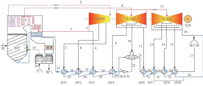
采用汽轮机高位布置技术的机组与常规机组的主要区别在于汽轮机运转层和排汽管道层的标高,采用汽轮机高位布置技术的汽轮机运转层的标高为65 m,排汽管道层的标高为43 m。采用汽轮机高位布置技术的发电机组系统图如图1 所示,锅炉为一次中间再热、超临界压力、变压运行的π型直流锅炉;汽轮机为一次中间再热空冷式机组,主蒸汽压力及温度分别为25.8 MPa、600 ℃,一次再热蒸汽压力及温度分别为5.4 MPa、620 ℃,排汽压力为10.5 kPa。
图1
图1
采用汽轮机高位布置技术的机组系统图
1—37为机组中各流股的编号;HT1—HT4为高压加热器,HT6—HT9为低压加热器,加热器按照抽汽压力由大到小编号;SCR为选择性催化还原。
Fig. 1
System diagram of the unit with high-level layout technology of turbine
2.2 汽轮机高位布置技术的模型验证
为了验证采用汽轮机高位布置技术的发电机组变工况计算模型的可靠性,在汽轮机热耗率验收(turbine heat acceptance,THA)、75%THA、50%THA、30%THA以及汽轮机额定功率(turbine rated power,TRL)工况下,对汽轮机变工况计算结果与原则性热力系统图进行对比,机组的主要参数如表2 所示,回热系统相关参数如表3 所示。
汽轮机抽汽压力模拟数据和实际数据对比如表4 所示。各级抽汽压力绝对误差均在0.1 MPa之内,模型计算精度满足要求。
3 结果与讨论
3.1 㶲分析
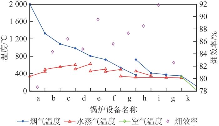
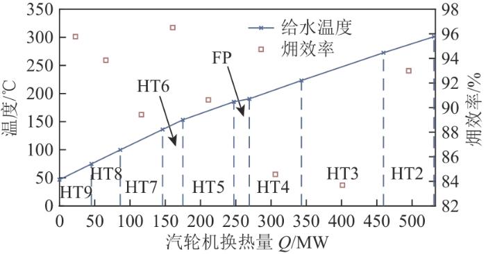
通过模拟得到了100%THA工况下采用汽轮机高位布置技术的燃煤机组的锅炉和汽轮机各设备的㶲效率变化情况(在该工况下运行时,去掉了最后一级高压加热器)。锅炉中各设备的温度和㶲效率变化如图2 所示,可以看出,锅炉中炉膛的烟气和水换热的㶲效率最低,这是因为该过程中水由液态水转化为气态水,热量主要用于增加水的显热。回热加热器的温度和㶲效率变化如图3 所示,可以看出,回热加热器中高压加热器的㶲效率明显低于低压加热器,存在较大的不可逆性,可通过优化高压加热器部分,减小系统的不可逆性,从而提高机组的效率。
图2
图2
锅炉中各设备的温度和㶲效率变化
a—炉膛;b—屏式过热器;c—高温过热器;d—高温再热器;e—低温再热器垂直段;f—低温过热器;g—低过侧省煤器;h—低温再热器水平段;i—低再侧省煤器;j—分级省煤器;k—空气预热器。
Fig. 2
Change of temperature and exergy efficiency of each equipment in the boiler
图3
图3
回热器加热器的温度和㶲效率变化
HT2—HT9为回热加热器;FP为给水泵。
Fig. 3
Change of temperature and exergy efficiency of regenerator heater
3.2 㶲经济性分析
选取的煤种为神华煤种,其特性参数如表5 所示。根据2019—2021年的平均煤价[31 ] ,选取的煤价为0.03元/MJ。根据国华锦界电厂的数据建立成本模型,锅炉中各设备尺寸及材料参数[32 ] 如表6 所示。不同类型组件的质量因子F BM [32 ] 如表7 所示。受限于地理环境因素,机组采用空冷凝汽器,具体的布置方案为8×8,每台机组共有640片换热管束,其中顺流管束480片,逆流管束160片。
整个燃煤机组的成本接近3 400元/kW,低于常规660 MW机组的成本。根据各组分C PE, k C EL 、平均维修费用C OML 和平均年燃料费用C FL 占12亿元平均年支出的27%、7%和66%,最终的度电成本为0.332 4元/(kW⋅h),这与电站公布的上网电价0.33元/(kW⋅h)[4 ] 相吻合。
各流股的㶲和㶲经济性数据如表8 所示,各设备的㶲和㶲经济性分析如表9 所示。在燃煤系统中,化学反应和传热过程一直是机组中熵产的最大来源。通过分析各流股的成本变化,得到优化程度最大的部件为低压加热器。
3.3 变工况㶲经济性分析
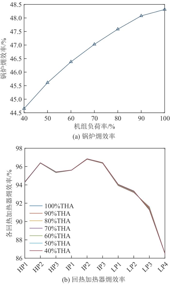
采用汽轮机高位布置技术的燃煤机组变工况时,锅炉的㶲效率降低,但是回热加热器的㶲效率不变,如图4 所示。当机组负荷为100%THA时,锅炉的㶲效率为48.3%;当机组负荷为40%THA时,锅炉的㶲效率为44.7%。
图4
图4
变负荷工况下的㶲效率
Fig. 4
Exergy efficiency under variable load conditions
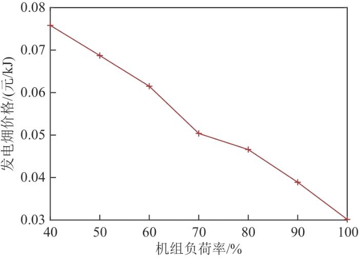
在变工况运行时,发电的平均㶲价格变化如图5 所示。当机组负荷为100%THA时,发电㶲价格为0.030 2元/kJ;当机组负荷为40%THA时,发电㶲价格为0.075 8元/kJ。因此,当机组满负荷运行时,机组的经济性更优。
图5
图5
变负荷工况下的发电㶲价格
Fig. 5
Exergy cost of electricity under variable load conditions
4 结论
建立了采用汽轮机高位布置技术的燃煤机组的㶲模型和㶲经济性模型,得到了机组不可逆性分布,分析了燃煤机组变工况下的流股、设备㶲效率变化以及成本变化,得到如下结论:
1)通过对锅炉各部件的㶲效率进行分析发现,炉膛的㶲效率最低,这主要是由化学反应以及辐射传热的损失过大导致的。
2)从机组的不可逆性分布可知,回热加热器中高压加热器的㶲效率存在较大的不可逆性,可通过优化该部分来减小系统的不可逆性,从而提高机组的效率。
3)通过对流股和设备的㶲成本进行分析,得到采用汽轮机高位布置技术的燃煤机组度电成本为0.332 4元/(kW⋅h)。
4)发电的㶲价格随着负荷的下降而升高,下一步可通过减小低负荷运行时机组的不可逆性来降低低负荷的发电㶲价格。
参考文献
View Option
[1]
HE F LIU X WANG M et al Energy,exergy,exergoeconomic,and environmental analyses and multi-objective optimization of a biomass-to-energy integrated thermal power plant
[J].Alexandria Engineering Journal ,2022 ,61 (7 ):5629 -5648 . doi:10.1016/j.aej.2021.11.016
[本文引用: 1]
[2]
张国柱 ,张钧泰 ,文钰 ,等 燃煤机组烟气余热及水回收系统变工况特性和调控策略
[J].中国电力 ,2022 ,55 (4 ):214 -220 .
[本文引用: 1]
ZHANG G Z ZHANG J T WEN Y et al Study on off-design condition characteristics and control strategy of fluegas waste heat and water recovery system of coal-fired power plants
[J].Electric Power ,2022 ,55 (4 ):214 -220 .
[本文引用: 1]
[4]
符悦 ,雷宇 ,刘明 ,等 不同进汽温度火电机组多压冷端系统综合性能分析
[J].中国电机工程学报 ,2022 ,42 (1 ):229 -238 .
[本文引用: 2]
FU Y LEI Y LIU M et al Performance evaluation on multi-pressure cold-end systems of thermal power plants with different inlet temperatures
[J].Proceedings of the CSEE ,2022 ,42 (1 ):229 -238 .
[本文引用: 2]
[5]
陈娜娜 ,韩小渠 ,穆祺伟 ,等 1 000 MW燃煤机组变负荷环境影响评价
[J].工程热物理学报 ,2019 ,40 (1 ):22 -27 .
[本文引用: 1]
CHEN N N HAN X Q MU Q W et al Environmental impact assessment on 1 000 MW coal-fired power plant under off-design conditions
[J].Journal of Engineering Thermophysics ,2019 ,40 (1 ):22 -27 .
[本文引用: 1]
[6]
宋畅 ,尹武昌 ,余学海 ,等 1 000 MW近零排放燃煤机组细颗粒物及SO3 排放和分布特征
[J].中国电机工程学报 ,2022 ,42 (5 ):1867 -1875 .
SONG C YIN W C YU X H et al Emission and distribution characteristics of fine particulate matter and SO3 in 1 000 MW near-zero emission coal-fired unit
[J].Proceedings of the CSEE ,2022 ,42 (5 ):1867 -1875 .
[7]
於震跃 ,徐红波 ,郑应霞 ,等 提高二次再热机组参数的技术经济研究
[J].浙江电力 ,2022 ,41 (9 ):101 -106 .
YU Z Y XU H B ZHENG Y X et al Technical and economic study on improving parameters of double reheat units
[J].Zhejiang Electric Power ,2022 ,41 (9 ):101 -106 .
[8]
[本文引用: 1]
ZHANG Q B ZHOU Q F Research on the development path of China’s thermal power generation technology based on the goal of “carbon peak and carbon neutralization”
[J].Power Generation Technology ,2023 ,44 (2 ):143 -154 . doi:10.12096/j.2096-4528.pgt.22092
[本文引用: 1]
[9]
[本文引用: 1]
ZHOU G B BIAN S CHEN Z Y et al Experimental study on high-temperature low cycle fatigue performance of inconel 617 and C-HRA-2 alloys for advanced ultra-supercritical units
[J].Journal of Chinese Society of Power Engineering ,2022 ,42 (5 ):475 -483 . doi:10.19805/j.cnki.jcspe.2022.05.012
[本文引用: 1]
[11]
XU C GAO Y XU G et al A thermodynamic analysis and economic evaluation of an integrated coldend energy utilization system in a de-carbonization coal-fired power plant
[J].Energy Conversion and Management ,2019 ,180 :218 -230 . doi:10.1016/j.enconman.2018.10.081
[本文引用: 1]
[12]
王婧 ,段立强 ,杨金福 ,等 集成BEST的700 ℃一次再热超超临界机组回热系统节能优化
[J].动力工程学报 ,2022 ,42 (7 ):632 -641 .
[本文引用: 1]
WANG J DUAN L Q YANG J F et al Energy saving optimization study on regenerative system of 700 ℃ single reheat ultra-supercritical unit with BEST
[J].Journal of Chinese Society of Power Engineering ,2022 ,42 (7 ):632 -641 .
[本文引用: 1]
[14]
LIU S L ZHOU G B WANG X et al Research on reliability probability of srss method for multi-point displacement of foundation of H-class gas turbine in high position
[J].Southern Energy Construction ,2022 ,9 (4 ):159 -166 . doi:10.16516/j.gedi.issn2095-8676.2022.04.020
[16]
张精桥 ,杜小军 ,张研 超超临界2×660 MW汽轮机高位布置给水泵选型与优化研究
[J].能源科技 ,2021 ,19 (2 ):49 -52 .
[本文引用: 1]
ZHANG J Q DU X J ZHANG Y Study on selection and optimization of feedwater pump for high level arranged ultra-supercritical 2×660 MW steam turbine
[J].Energy Science and Technology ,2021 ,19 (2 ):49 -52 .
[本文引用: 1]
[17]
罗建松 ,叶勇健 700 ℃先进超超临界机组概念设计方案研究
[J].热力发电 ,2022 ,51 (8 ):99 -107 .
[本文引用: 1]
LUO J S YE Y J Study on conceptual design scheme of 700 ℃ advanced ultra supercritical unit
[J].Thermal Power Generation ,2022 ,51 (8 ):99 -107 .
[本文引用: 1]
[18]
YE X DONG Z LU J et al Thermoeconomic evaluation of double-reheat coal-fired power units with carbon capture and storage and waste heat recovery using organic Rankine cycle
[J].International Journal of Greenhouse Gas Control ,2021 ,105 (1 ):103247 . doi:10.1016/j.ijggc.2020.103247
[本文引用: 1]
[19]
WU X SHEN J LI Y et al Flexible operation of post-combustion solvent-based carbon capture for coal-fired power plants using multi-model predictive control:a simulation study
[J].Fuel ,2018 ,220 :931 -941 . doi:10.1016/j.fuel.2018.02.061
[20]
付亦葳 ,谢天 ,屈杰 一次、二次再热机组汽轮机高低位布置方案热经济性分析
[J].热力发电 ,2017 ,46 (7 ):1 -4 .
[本文引用: 1]
FU Y W XIE T QU J Thermal-economic analysis for scheme of steam turbine generator placement in high and low platform separately
[J].Thermal Power Generation ,2017 ,46 (7 ):1 -4 .
[本文引用: 1]
[21]
AMROLLAHI Z ERTESVÅG I S BOLLAND O Optimized process configurations of post-combustion CO2 capture for natural-gas-fired power plant:exergy analysis
[J].International Journal of Greenhouse Gas Control ,2011 ,5 (6 ):1393 -1405 . doi:10.1016/j.ijggc.2011.09.004
[本文引用: 1]
[23]
AHMADI G R TOGHRAIE D Energy and exergy analysis of montazeri steam power plant in Iran
[J].Renewable and Sustainable Energy Reviews ,2016 ,56 :454 -463 . doi:10.1016/j.rser.2015.11.074
[本文引用: 1]
[24]
KIM S LIM Y I LEE D et al Perspectives of oxy-coal power plants equipped with CO2 capture,utilization,and storage in terms of energy,economic,and environmental impacts
[J].Energy Conversion and Management ,2022 ,273 :116361 . doi:10.1016/j.enconman.2022.116361
[本文引用: 1]
[25]
ZHOU L XU G ZHAO S et al Parametric analysis and process optimization of steam cycle in double reheat ultra-supercritical power plants
[J].Applied Thermal Engineering ,2016 ,99 :652 -660 . doi:10.1016/j.applthermaleng.2016.01.047
[本文引用: 2]
[26]
YAN H LIU M WANG Z et al Flexibility enhancement of solar-aided coal-fired power plant under different direct normal irradiance conditions
[J].Energy ,2023 ,262 :125349 . doi:10.1016/j.energy.2022.125349
[本文引用: 1]
[27]
ZHANG Z ZHOU R GE X et al Perspectives for 700 ℃ ultra-supercritical power generation:thermal safety of high-temperature heating surfaces
[J].Energy ,2020 ,190 :116411 . doi:10.1016/j.energy.2019.116411
[本文引用: 1]
[28]
FU Y ZHAO Y LIU M et al Optimization of cold-end system of thermal power plants based on entropy generation minimization
[J].Frontiers in Energy ,2022 ,16 (6 ):956 -972 . doi:10.1007/s11708-021-0785-5
[本文引用: 1]
[29]
LAZZARETTO A TSATSARONIS G SPECO:a systematic and general methodology for calculating efficiencies and costs in thermal systems
[J].Energy ,2006 ,31 (8/9 ):1257 -1289 . doi:10.1016/j.energy.2005.03.011
[本文引用: 1]
[30]
BARTELA L SKOREK-OSIKOWSKA A KOTOWICZ J An analysis of the investment risk related to the integration of a supercritical coal-fired combined heat and power plant with an absorption installation for CO2 separation
[J].Applied Energy ,2015 ,156 :423 -435 . doi:10.1016/j.apenergy.2015.07.045
[本文引用: 2]
[31]
SU Z YANG L A novel and efficient cogeneration system of waste heat recovery integrated carbon capture and dehumidification for coal-fired power plants
[J].Energy Conversion and Management ,2022 ,255 :115358 . doi:10.1016/j.enconman.2022.115358
[本文引用: 1]
[32]
Chemical Engineering World Group Analysis,synthesis and design of chemical processes
[J].Chemical Engineering World ,2016 ,51 (12 ):129 .
[本文引用: 2]
Energy,exergy,exergoeconomic,and environmental analyses and multi-objective optimization of a biomass-to-energy integrated thermal power plant
1
2022
... 燃煤发电是电力供应的主要形式,国际能源署( International Energy Agency,IEA)在《2021年煤炭报告》中称,2021年电力需求增长超过了低碳能源供给能力,导致燃煤发电厂的发电量猛增9%[1 ] .在经历2021年的能源短缺危机后,煤炭等传统能源在现阶段的能源系统中仍占据主导地位.然而,煤炭作为全球电力发展的基石,发展节能减排技术至关重要[2 -3 ] . ...
燃煤机组烟气余热及水回收系统变工况特性和调控策略
1
2022
... 燃煤发电是电力供应的主要形式,国际能源署( International Energy Agency,IEA)在《2021年煤炭报告》中称,2021年电力需求增长超过了低碳能源供给能力,导致燃煤发电厂的发电量猛增9%[1 ] .在经历2021年的能源短缺危机后,煤炭等传统能源在现阶段的能源系统中仍占据主导地位.然而,煤炭作为全球电力发展的基石,发展节能减排技术至关重要[2 -3 ] . ...
Study on off-design condition characteristics and control strategy of fluegas waste heat and water recovery system of coal-fired power plants
1
2022
... 燃煤发电是电力供应的主要形式,国际能源署( International Energy Agency,IEA)在《2021年煤炭报告》中称,2021年电力需求增长超过了低碳能源供给能力,导致燃煤发电厂的发电量猛增9%[1 ] .在经历2021年的能源短缺危机后,煤炭等传统能源在现阶段的能源系统中仍占据主导地位.然而,煤炭作为全球电力发展的基石,发展节能减排技术至关重要[2 -3 ] . ...
绿电与绿氢耦合煤化工的系统建设方案
1
2023
... 燃煤发电是电力供应的主要形式,国际能源署( International Energy Agency,IEA)在《2021年煤炭报告》中称,2021年电力需求增长超过了低碳能源供给能力,导致燃煤发电厂的发电量猛增9%[1 ] .在经历2021年的能源短缺危机后,煤炭等传统能源在现阶段的能源系统中仍占据主导地位.然而,煤炭作为全球电力发展的基石,发展节能减排技术至关重要[2 -3 ] . ...
Construction scheme for the system coupling coal chemical industry with green electricity and green hydrogen
1
2023
... 燃煤发电是电力供应的主要形式,国际能源署( International Energy Agency,IEA)在《2021年煤炭报告》中称,2021年电力需求增长超过了低碳能源供给能力,导致燃煤发电厂的发电量猛增9%[1 ] .在经历2021年的能源短缺危机后,煤炭等传统能源在现阶段的能源系统中仍占据主导地位.然而,煤炭作为全球电力发展的基石,发展节能减排技术至关重要[2 -3 ] . ...
不同进汽温度火电机组多压冷端系统综合性能分析
2
2022
... 节能减排作为我国火力发电行业的研究热点,目前研究主要集中在降低热端不可逆损失、减少系统内部不可逆损失及降低冷端不可逆损失3个方面[4 ] .在降低热端不可逆损失的研究中,以提高主蒸汽和再热蒸汽参数作为优化的主要手段,高参数超超临界燃煤发电技术能够有效提升机组效率,并且减少温室气体的排放[5 -8 ] .但是,由于耐高温材料阻碍高参数超超临界燃煤发电技术的发展[9 ] ,目前的主蒸汽温度最高为605 ℃,再热蒸汽温度最高达到620 ℃[10 ] .机组的冷端受限于地理条件,这部分不可逆损失的研究主要集中于冷端构型设计[11 ] . ...
... 整个燃煤机组的成本接近3 400元/kW,低于常规660 MW机组的成本.根据各组分C PE, k C EL 、平均维修费用C OML 和平均年燃料费用C FL 占12亿元平均年支出的27%、7%和66%,最终的度电成本为0.332 4元/(kW⋅h),这与电站公布的上网电价0.33元/(kW⋅h)[4 ] 相吻合. ...
Performance evaluation on multi-pressure cold-end systems of thermal power plants with different inlet temperatures
2
2022
... 节能减排作为我国火力发电行业的研究热点,目前研究主要集中在降低热端不可逆损失、减少系统内部不可逆损失及降低冷端不可逆损失3个方面[4 ] .在降低热端不可逆损失的研究中,以提高主蒸汽和再热蒸汽参数作为优化的主要手段,高参数超超临界燃煤发电技术能够有效提升机组效率,并且减少温室气体的排放[5 -8 ] .但是,由于耐高温材料阻碍高参数超超临界燃煤发电技术的发展[9 ] ,目前的主蒸汽温度最高为605 ℃,再热蒸汽温度最高达到620 ℃[10 ] .机组的冷端受限于地理条件,这部分不可逆损失的研究主要集中于冷端构型设计[11 ] . ...
... 整个燃煤机组的成本接近3 400元/kW,低于常规660 MW机组的成本.根据各组分C PE, k C EL 、平均维修费用C OML 和平均年燃料费用C FL 占12亿元平均年支出的27%、7%和66%,最终的度电成本为0.332 4元/(kW⋅h),这与电站公布的上网电价0.33元/(kW⋅h)[4 ] 相吻合. ...
1 000 MW燃煤机组变负荷环境影响评价
1
2019
... 节能减排作为我国火力发电行业的研究热点,目前研究主要集中在降低热端不可逆损失、减少系统内部不可逆损失及降低冷端不可逆损失3个方面[4 ] .在降低热端不可逆损失的研究中,以提高主蒸汽和再热蒸汽参数作为优化的主要手段,高参数超超临界燃煤发电技术能够有效提升机组效率,并且减少温室气体的排放[5 -8 ] .但是,由于耐高温材料阻碍高参数超超临界燃煤发电技术的发展[9 ] ,目前的主蒸汽温度最高为605 ℃,再热蒸汽温度最高达到620 ℃[10 ] .机组的冷端受限于地理条件,这部分不可逆损失的研究主要集中于冷端构型设计[11 ] . ...
Environmental impact assessment on 1 000 MW coal-fired power plant under off-design conditions
1
2019
... 节能减排作为我国火力发电行业的研究热点,目前研究主要集中在降低热端不可逆损失、减少系统内部不可逆损失及降低冷端不可逆损失3个方面[4 ] .在降低热端不可逆损失的研究中,以提高主蒸汽和再热蒸汽参数作为优化的主要手段,高参数超超临界燃煤发电技术能够有效提升机组效率,并且减少温室气体的排放[5 -8 ] .但是,由于耐高温材料阻碍高参数超超临界燃煤发电技术的发展[9 ] ,目前的主蒸汽温度最高为605 ℃,再热蒸汽温度最高达到620 ℃[10 ] .机组的冷端受限于地理条件,这部分不可逆损失的研究主要集中于冷端构型设计[11 ] . ...
1 000 MW近零排放燃煤机组细颗粒物及SO3 排放和分布特征
0
2022
Emission and distribution characteristics of fine particulate matter and SO3 in 1 000 MW near-zero emission coal-fired unit
0
2022
Technical and economic study on improving parameters of double reheat units
0
2022
基于“双碳”目标的中国火力发电技术发展路径研究
1
2023
... 节能减排作为我国火力发电行业的研究热点,目前研究主要集中在降低热端不可逆损失、减少系统内部不可逆损失及降低冷端不可逆损失3个方面[4 ] .在降低热端不可逆损失的研究中,以提高主蒸汽和再热蒸汽参数作为优化的主要手段,高参数超超临界燃煤发电技术能够有效提升机组效率,并且减少温室气体的排放[5 -8 ] .但是,由于耐高温材料阻碍高参数超超临界燃煤发电技术的发展[9 ] ,目前的主蒸汽温度最高为605 ℃,再热蒸汽温度最高达到620 ℃[10 ] .机组的冷端受限于地理条件,这部分不可逆损失的研究主要集中于冷端构型设计[11 ] . ...
Research on the development path of China’s thermal power generation technology based on the goal of “carbon peak and carbon neutralization”
1
2023
... 节能减排作为我国火力发电行业的研究热点,目前研究主要集中在降低热端不可逆损失、减少系统内部不可逆损失及降低冷端不可逆损失3个方面[4 ] .在降低热端不可逆损失的研究中,以提高主蒸汽和再热蒸汽参数作为优化的主要手段,高参数超超临界燃煤发电技术能够有效提升机组效率,并且减少温室气体的排放[5 -8 ] .但是,由于耐高温材料阻碍高参数超超临界燃煤发电技术的发展[9 ] ,目前的主蒸汽温度最高为605 ℃,再热蒸汽温度最高达到620 ℃[10 ] .机组的冷端受限于地理条件,这部分不可逆损失的研究主要集中于冷端构型设计[11 ] . ...
先进超超临界机组用Inconel 617与C-HRA-2合金高温低周疲劳性能试验研究
1
2022
... 节能减排作为我国火力发电行业的研究热点,目前研究主要集中在降低热端不可逆损失、减少系统内部不可逆损失及降低冷端不可逆损失3个方面[4 ] .在降低热端不可逆损失的研究中,以提高主蒸汽和再热蒸汽参数作为优化的主要手段,高参数超超临界燃煤发电技术能够有效提升机组效率,并且减少温室气体的排放[5 -8 ] .但是,由于耐高温材料阻碍高参数超超临界燃煤发电技术的发展[9 ] ,目前的主蒸汽温度最高为605 ℃,再热蒸汽温度最高达到620 ℃[10 ] .机组的冷端受限于地理条件,这部分不可逆损失的研究主要集中于冷端构型设计[11 ] . ...
Experimental study on high-temperature low cycle fatigue performance of inconel 617 and C-HRA-2 alloys for advanced ultra-supercritical units
1
2022
... 节能减排作为我国火力发电行业的研究热点,目前研究主要集中在降低热端不可逆损失、减少系统内部不可逆损失及降低冷端不可逆损失3个方面[4 ] .在降低热端不可逆损失的研究中,以提高主蒸汽和再热蒸汽参数作为优化的主要手段,高参数超超临界燃煤发电技术能够有效提升机组效率,并且减少温室气体的排放[5 -8 ] .但是,由于耐高温材料阻碍高参数超超临界燃煤发电技术的发展[9 ] ,目前的主蒸汽温度最高为605 ℃,再热蒸汽温度最高达到620 ℃[10 ] .机组的冷端受限于地理条件,这部分不可逆损失的研究主要集中于冷端构型设计[11 ] . ...
Thermoeconomic operation optimization of a coal-fired power plant
1
2012
... 节能减排作为我国火力发电行业的研究热点,目前研究主要集中在降低热端不可逆损失、减少系统内部不可逆损失及降低冷端不可逆损失3个方面[4 ] .在降低热端不可逆损失的研究中,以提高主蒸汽和再热蒸汽参数作为优化的主要手段,高参数超超临界燃煤发电技术能够有效提升机组效率,并且减少温室气体的排放[5 -8 ] .但是,由于耐高温材料阻碍高参数超超临界燃煤发电技术的发展[9 ] ,目前的主蒸汽温度最高为605 ℃,再热蒸汽温度最高达到620 ℃[10 ] .机组的冷端受限于地理条件,这部分不可逆损失的研究主要集中于冷端构型设计[11 ] . ...
A thermodynamic analysis and economic evaluation of an integrated coldend energy utilization system in a de-carbonization coal-fired power plant
1
2019
... 节能减排作为我国火力发电行业的研究热点,目前研究主要集中在降低热端不可逆损失、减少系统内部不可逆损失及降低冷端不可逆损失3个方面[4 ] .在降低热端不可逆损失的研究中,以提高主蒸汽和再热蒸汽参数作为优化的主要手段,高参数超超临界燃煤发电技术能够有效提升机组效率,并且减少温室气体的排放[5 -8 ] .但是,由于耐高温材料阻碍高参数超超临界燃煤发电技术的发展[9 ] ,目前的主蒸汽温度最高为605 ℃,再热蒸汽温度最高达到620 ℃[10 ] .机组的冷端受限于地理条件,这部分不可逆损失的研究主要集中于冷端构型设计[11 ] . ...
集成BEST的700 ℃一次再热超超临界机组回热系统节能优化
1
2022
... 除了通过提高热端参数和降低冷端参数来提升机组效率,还可以通过调整机组的三维结构[12 ] 来提升机组的经济性.采用汽轮机高位布置技术能大幅减少耐高温管道的使用,从而提升机组的经济性[13 -15 ] .虽然目前汽轮机高位布置技术已经成熟[16 -17 ] ,但是现有研究大多从热力学第一定律的角度进行分析[18 -20 ] ,鲜少对采用汽轮机高位布置技术的机组不可逆性进行分析. ...
Energy saving optimization study on regenerative system of 700 ℃ single reheat ultra-supercritical unit with BEST
1
2022
... 除了通过提高热端参数和降低冷端参数来提升机组效率,还可以通过调整机组的三维结构[12 ] 来提升机组的经济性.采用汽轮机高位布置技术能大幅减少耐高温管道的使用,从而提升机组的经济性[13 -15 ] .虽然目前汽轮机高位布置技术已经成熟[16 -17 ] ,但是现有研究大多从热力学第一定律的角度进行分析[18 -20 ] ,鲜少对采用汽轮机高位布置技术的机组不可逆性进行分析. ...
高位布置660 MW汽轮机组设计特点与安全性研究
1
2021
... 除了通过提高热端参数和降低冷端参数来提升机组效率,还可以通过调整机组的三维结构[12 ] 来提升机组的经济性.采用汽轮机高位布置技术能大幅减少耐高温管道的使用,从而提升机组的经济性[13 -15 ] .虽然目前汽轮机高位布置技术已经成熟[16 -17 ] ,但是现有研究大多从热力学第一定律的角度进行分析[18 -20 ] ,鲜少对采用汽轮机高位布置技术的机组不可逆性进行分析. ...
Design characteristics and research on safety of high-level layout 660 MW steam turbine
1
2021
... 除了通过提高热端参数和降低冷端参数来提升机组效率,还可以通过调整机组的三维结构[12 ] 来提升机组的经济性.采用汽轮机高位布置技术能大幅减少耐高温管道的使用,从而提升机组的经济性[13 -15 ] .虽然目前汽轮机高位布置技术已经成熟[16 -17 ] ,但是现有研究大多从热力学第一定律的角度进行分析[18 -20 ] ,鲜少对采用汽轮机高位布置技术的机组不可逆性进行分析. ...
高位布置H级燃机基础多点位移SRSS法可靠概率研究
0
2022
Research on reliability probability of srss method for multi-point displacement of foundation of H-class gas turbine in high position
0
2022
低温场景超临界CO2 循环燃煤发电系统研究
1
2022
... 除了通过提高热端参数和降低冷端参数来提升机组效率,还可以通过调整机组的三维结构[12 ] 来提升机组的经济性.采用汽轮机高位布置技术能大幅减少耐高温管道的使用,从而提升机组的经济性[13 -15 ] .虽然目前汽轮机高位布置技术已经成熟[16 -17 ] ,但是现有研究大多从热力学第一定律的角度进行分析[18 -20 ] ,鲜少对采用汽轮机高位布置技术的机组不可逆性进行分析. ...
Study on supercritical CO2 cycle coal-fired power generation system for low temperature scenario
1
2022
... 除了通过提高热端参数和降低冷端参数来提升机组效率,还可以通过调整机组的三维结构[12 ] 来提升机组的经济性.采用汽轮机高位布置技术能大幅减少耐高温管道的使用,从而提升机组的经济性[13 -15 ] .虽然目前汽轮机高位布置技术已经成熟[16 -17 ] ,但是现有研究大多从热力学第一定律的角度进行分析[18 -20 ] ,鲜少对采用汽轮机高位布置技术的机组不可逆性进行分析. ...
超超临界2×660 MW汽轮机高位布置给水泵选型与优化研究
1
2021
... 除了通过提高热端参数和降低冷端参数来提升机组效率,还可以通过调整机组的三维结构[12 ] 来提升机组的经济性.采用汽轮机高位布置技术能大幅减少耐高温管道的使用,从而提升机组的经济性[13 -15 ] .虽然目前汽轮机高位布置技术已经成熟[16 -17 ] ,但是现有研究大多从热力学第一定律的角度进行分析[18 -20 ] ,鲜少对采用汽轮机高位布置技术的机组不可逆性进行分析. ...
Study on selection and optimization of feedwater pump for high level arranged ultra-supercritical 2×660 MW steam turbine
1
2021
... 除了通过提高热端参数和降低冷端参数来提升机组效率,还可以通过调整机组的三维结构[12 ] 来提升机组的经济性.采用汽轮机高位布置技术能大幅减少耐高温管道的使用,从而提升机组的经济性[13 -15 ] .虽然目前汽轮机高位布置技术已经成熟[16 -17 ] ,但是现有研究大多从热力学第一定律的角度进行分析[18 -20 ] ,鲜少对采用汽轮机高位布置技术的机组不可逆性进行分析. ...
700 ℃先进超超临界机组概念设计方案研究
1
2022
... 除了通过提高热端参数和降低冷端参数来提升机组效率,还可以通过调整机组的三维结构[12 ] 来提升机组的经济性.采用汽轮机高位布置技术能大幅减少耐高温管道的使用,从而提升机组的经济性[13 -15 ] .虽然目前汽轮机高位布置技术已经成熟[16 -17 ] ,但是现有研究大多从热力学第一定律的角度进行分析[18 -20 ] ,鲜少对采用汽轮机高位布置技术的机组不可逆性进行分析. ...
Study on conceptual design scheme of 700 ℃ advanced ultra supercritical unit
1
2022
... 除了通过提高热端参数和降低冷端参数来提升机组效率,还可以通过调整机组的三维结构[12 ] 来提升机组的经济性.采用汽轮机高位布置技术能大幅减少耐高温管道的使用,从而提升机组的经济性[13 -15 ] .虽然目前汽轮机高位布置技术已经成熟[16 -17 ] ,但是现有研究大多从热力学第一定律的角度进行分析[18 -20 ] ,鲜少对采用汽轮机高位布置技术的机组不可逆性进行分析. ...
Thermoeconomic evaluation of double-reheat coal-fired power units with carbon capture and storage and waste heat recovery using organic Rankine cycle
1
2021
... 除了通过提高热端参数和降低冷端参数来提升机组效率,还可以通过调整机组的三维结构[12 ] 来提升机组的经济性.采用汽轮机高位布置技术能大幅减少耐高温管道的使用,从而提升机组的经济性[13 -15 ] .虽然目前汽轮机高位布置技术已经成熟[16 -17 ] ,但是现有研究大多从热力学第一定律的角度进行分析[18 -20 ] ,鲜少对采用汽轮机高位布置技术的机组不可逆性进行分析. ...
Flexible operation of post-combustion solvent-based carbon capture for coal-fired power plants using multi-model predictive control:a simulation study
0
2018
一次、二次再热机组汽轮机高低位布置方案热经济性分析
1
2017
... 除了通过提高热端参数和降低冷端参数来提升机组效率,还可以通过调整机组的三维结构[12 ] 来提升机组的经济性.采用汽轮机高位布置技术能大幅减少耐高温管道的使用,从而提升机组的经济性[13 -15 ] .虽然目前汽轮机高位布置技术已经成熟[16 -17 ] ,但是现有研究大多从热力学第一定律的角度进行分析[18 -20 ] ,鲜少对采用汽轮机高位布置技术的机组不可逆性进行分析. ...
Thermal-economic analysis for scheme of steam turbine generator placement in high and low platform separately
1
2017
... 除了通过提高热端参数和降低冷端参数来提升机组效率,还可以通过调整机组的三维结构[12 ] 来提升机组的经济性.采用汽轮机高位布置技术能大幅减少耐高温管道的使用,从而提升机组的经济性[13 -15 ] .虽然目前汽轮机高位布置技术已经成熟[16 -17 ] ,但是现有研究大多从热力学第一定律的角度进行分析[18 -20 ] ,鲜少对采用汽轮机高位布置技术的机组不可逆性进行分析. ...
Optimized process configurations of post-combustion CO2 capture for natural-gas-fired power plant:exergy analysis
1
2011
... 通过㶲分析可以评估系统的不可逆性分布,为系统优化提供参考[21 ] .采用汽轮机高位布置的燃煤机组热力性能变化规律与常规布置机组相似[22 ] ,但是就投资成本而言,采用汽轮机高位布置的燃煤机组土建结构投资成本比常规布置机组成本高.因此,有必要对采用汽轮机高位布置的燃煤机组的㶲经济性变化规律进行研究. ...
基于改进粒子群算法的超超临界燃煤机组负荷系统建模
1
2021
... 通过㶲分析可以评估系统的不可逆性分布,为系统优化提供参考[21 ] .采用汽轮机高位布置的燃煤机组热力性能变化规律与常规布置机组相似[22 ] ,但是就投资成本而言,采用汽轮机高位布置的燃煤机组土建结构投资成本比常规布置机组成本高.因此,有必要对采用汽轮机高位布置的燃煤机组的㶲经济性变化规律进行研究. ...
Load system modeling of ultra-supercritical coal-fired power unit based on improved particle swarm optimization
1
2021
... 通过㶲分析可以评估系统的不可逆性分布,为系统优化提供参考[21 ] .采用汽轮机高位布置的燃煤机组热力性能变化规律与常规布置机组相似[22 ] ,但是就投资成本而言,采用汽轮机高位布置的燃煤机组土建结构投资成本比常规布置机组成本高.因此,有必要对采用汽轮机高位布置的燃煤机组的㶲经济性变化规律进行研究. ...
Energy and exergy analysis of montazeri steam power plant in Iran
1
2016
... 假定㶲分析的环境参数如下:压力p 0 =0.1 MPa,温度T 0 =298.15 K.燃煤发电机组以水为介质,单位质量水的㶲计算公式[23 -24 ] 如下: ...
Perspectives of oxy-coal power plants equipped with CO2 capture,utilization,and storage in terms of energy,economic,and environmental impacts
1
2022
... 假定㶲分析的环境参数如下:压力p 0 =0.1 MPa,温度T 0 =298.15 K.燃煤发电机组以水为介质,单位质量水的㶲计算公式[23 -24 ] 如下: ...
Parametric analysis and process optimization of steam cycle in double reheat ultra-supercritical power plants
2
2016
... 典型的超超临界一次再热的发电机组成本约为5亿美元[25 ] ,采用汽轮机高位布置技术的发电机组增加了发电机组的购置成本,主要体现在剪力墙的费用上,该费用属于机组的固定成本,假定电厂运行年限为30年,与机组经济分析有关的参数如表1 所示.采用总收入(total revenue requirement,TRR)方法[26 ] 计算得到采购设备成本C PE 和固定资本成本C FC (C FC =C PE F BM ,其中F BM 为模块因子),成本按照化工工厂成本指数(chemical engineering plant cost index,CEPCI)上升到参考年. ...
... 为了进一步研究系统的㶲流情况和设备运行情况,文献[25 ]提出了通用的㶲经济性分析(specific exergy costing,SPECO)方法,通过计算物质、设备的㶲以及成本的关系,可以得到每股㶲的成本,其中流股i 的总㶲成本计算公式如下: ...
Flexibility enhancement of solar-aided coal-fired power plant under different direct normal irradiance conditions
1
2023
... 典型的超超临界一次再热的发电机组成本约为5亿美元[25 ] ,采用汽轮机高位布置技术的发电机组增加了发电机组的购置成本,主要体现在剪力墙的费用上,该费用属于机组的固定成本,假定电厂运行年限为30年,与机组经济分析有关的参数如表1 所示.采用总收入(total revenue requirement,TRR)方法[26 ] 计算得到采购设备成本C PE 和固定资本成本C FC (C FC =C PE F BM ,其中F BM 为模块因子),成本按照化工工厂成本指数(chemical engineering plant cost index,CEPCI)上升到参考年. ...
Perspectives for 700?℃ ultra-supercritical power generation:thermal safety of high-temperature heating surfaces
1
2020
... 根据火电工程限额设计参考造价指标中的数据[27 ] ,建立采用汽轮机高位布置技术的机组各部件购置成本(C PE, k [28 ] . ...
Optimization of cold-end system of thermal power plants based on entropy generation minimization
1
2022
... 根据火电工程限额设计参考造价指标中的数据[27 ] ,建立采用汽轮机高位布置技术的机组各部件购置成本(C PE, k [28 ] . ...
SPECO:a systematic and general methodology for calculating efficiencies and costs in thermal systems
1
2006
... 锅炉的成本一般占燃煤机组购置成本的50%[29 ] ,其计算公式如下: ...
An analysis of the investment risk related to the integration of a supercritical coal-fired combined heat and power plant with an absorption installation for CO2 separation
2
2015
... 依据文献[30 ],平均工程费用C EL 和平均维修费用C OML 依据电厂的总投资成本C TI 计算可得,其中: ...
... 式中:C PE, k k 的投资成本,元;C E L F , O M L C OML 的平均变化系数;γ 通常取4.75,φ 通常取0.06[30 ] . ...
A novel and efficient cogeneration system of waste heat recovery integrated carbon capture and dehumidification for coal-fired power plants
1
2022
... 选取的煤种为神华煤种,其特性参数如表5 所示.根据2019—2021年的平均煤价[31 ] ,选取的煤价为0.03元/MJ.根据国华锦界电厂的数据建立成本模型,锅炉中各设备尺寸及材料参数[32 ] 如表6 所示.不同类型组件的质量因子F BM [32 ] 如表7 所示.受限于地理环境因素,机组采用空冷凝汽器,具体的布置方案为8×8,每台机组共有640片换热管束,其中顺流管束480片,逆流管束160片. ...
Analysis,synthesis and design of chemical processes
2
2016
... 选取的煤种为神华煤种,其特性参数如表5 所示.根据2019—2021年的平均煤价[31 ] ,选取的煤价为0.03元/MJ.根据国华锦界电厂的数据建立成本模型,锅炉中各设备尺寸及材料参数[32 ] 如表6 所示.不同类型组件的质量因子F BM [32 ] 如表7 所示.受限于地理环境因素,机组采用空冷凝汽器,具体的布置方案为8×8,每台机组共有640片换热管束,其中顺流管束480片,逆流管束160片. ...
... [32 ]如表7 所示.受限于地理环境因素,机组采用空冷凝汽器,具体的布置方案为8×8,每台机组共有640片换热管束,其中顺流管束480片,逆流管束160片. ...


