0 引言
储能技术在削峰填谷、平滑负荷、提升负荷率的同时改善了部分火电机组的运行条件,使其从压荷状态变为稳定运行,减少了火电厂运行费用和发电成本[1 -2 ] 。储能系统的投入使电网负荷趋于合理,提高了调峰火电机组效率,甚至可延缓或减少电源、电网建设,提高能源和资产利用率,从而有效改变电力系统建设模式[3 -4 ] 。利用储能系统不仅能给传统火电机组带来可观的收益,还可使机组运行更平稳、安全、可靠,更适应电力系统需求的新模式,从而助力“双碳”目标的实现[5 -6 ] 。
目前市场上的电力储能技术种类繁多,但适用于火电机组大功率调峰的储能技术仅有熔盐储能[7 ] 、电化学储能[8 ] 及压缩空气储能[9 ] 3种。熔盐储能与火电机组耦合对原有火电机组热力系统影响较大,系统较为复杂,效率低。电化学储能容量偏小且存在安全风险。而压缩空气储能是可行性更高的一种大规模储能技术,其利用电能、热能及机械能相互转化,实现电能储存及释放,对火电机组影响较小,是一种安全可靠且可行的调峰储能技术[10 -11 ] 。
目前非补燃气态压缩空气储能系统已趋于成熟,其采用多级压缩、常温高压气态存储、多级膨胀发电的工艺系统。通过示范项目发现,制约该储能系统的因素较多,如最佳压缩机级数、压缩级间温度、储气室容积、透平入口温度等,系统电-电转化效率及储能密度整体偏低[12 ] 。液态压缩空气储能系统由于单位储能功率所需储气室体积小、效率高等优势而受到众多学者关注。何青等[13 ] 建立了液态空气储能系统的热力学模型和㶲分析模型,对系统内蓄热器热力特性及结构进行了研究分析。马兴民[14 ] 对深冷液化空气储能系统进行全面分析,提出了深冷液化空气储能系统设计的关键参数。苏要港等[15 ] 将液态压缩空气储能系统与液化天然气(liquefied natural gas,LNG)和有机朗肯循环(organic Rankine cycle,ORC)相结合,研究了多种ORC工质对系统能源利用率和㶲效率的影响。
目前,针对液态空气储能耦合外界冷热源以提升电-电转化效率的研究较多,但对非补燃液态压缩空气储能系统研究较少,系统内的压缩机级间温度、压缩机级数、透平入口温度等关键参数对储能效率的影响研究鲜见报道。为此,本文提出一种非补燃液态压缩空气储能系统,借助仿真软件搭建工艺系统模型,并对该系统压缩机组的关键参数进行计算分析,同时与非补燃气态压缩空气系统性能进行对比。研究结果可为后期液态空气储能系统设计及工程示范提供参考。
1 非补燃液态压缩空气储能系统
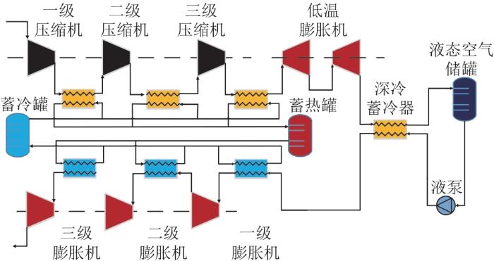
非补燃液态压缩空气储能系统原理如图1 所示。储能过程采用空气多级压缩、级间冷却,将压缩产生的热量通过导热油介质储存在蓄热罐内,压缩后通过级间换热器降温成为常温、高压状态,流进深冷膨胀机内膨胀、降温、降压,将常温、高压空气转为低温、低压空气,再通过蓄冷罐内深度冷却,将空气冷却到纯液态,储存在液态储罐中。释能过程液态空气经过液态升压泵升压,转为低温、高压状态,再通过蓄冷器吸热,将液态空气转为常温、高压气态空气,然后吸收蓄热罐内的高品质压缩热,转为高温、高压空气送入一级透平内做功发电;一级透平排气吸收蓄热罐内的热量,将空气加热升温,送入二级透平做功发电;二级透平排气吸收蓄热罐内的热量升温,送入末级透平做功发电;末级透平排气为常温、常压,直接排入大气环境中。
图1
图1
非补燃液态压缩空气储能系统原理图
Fig. 1
Schematic diagram of non-supplementary combustion liquid compressed air energy storage system
2 数学模型
液态压缩空气储能系统主要包括压缩蓄热系统、液态储能系统、膨胀做功系统3个子系统。其中:压缩蓄热系统主要包含多级压缩机及级间冷却换热器;液态储能系统主要包含蓄冷换热器、气液分离器、液态储存罐及液泵;膨胀做功系统主要包含多级膨胀机及级间加热器。针对系统流程特点,建立如下数学模型。
p o u t , i = π c p i n , i (1)
式中:p i n , i i 级压缩机进口压力;π c
T o u t , i = π c n - 1 n T i n , i (2)
式中:T i n , i i 级压缩机进口温度;n 为绝热指数。
T o u t , i - T i n , i = T i n , i ( π c n - 1 n - 1 ) (3)
W c , i = c p , i q m , i ( T o u t , i - T i n , i ) (4)
式中:c p , i i 级空气定压比热容;q m , i i 级空气质量流量。
W y = ∑ i = 1 N W c , i (5)
T o u t , Q , x = 1 - ε T i n , Q , x + ε T o i l , i n , x (6)
式中:T i n , Q , x x 级空气侧换热器进口温度;T o i l , i n , x x 级蓄热介质油的入口温度;ε
d Q x d t = c p , x ∆ m x ( T i n , Q , x - T o u t , Q , x ) (7)
式中:c p , x x 级空气定压比热容;∆ m x x 级空气质量;Q x x 级空气吸热量或放热量。
d Q x d t = c p , x ∆ m x ( T o u t , Q , x - T i n , Q , x ) (8)
Q k = ∫ d Q x (9)
p t , o u t = p t , i n / π t (10)
式中:p t , i n t 级透平进口压力;π t
T t , o u t = T t , i n / π t n - 1 n (11)
T t , i n - T t , o u t = T t , i n ( 1 - π t 1 - n n ) (12)
W t = c p , t q m , t ( T t , i n - T t , o u t ) (13)
式中:c p , t t 级空气定压比热容;q m , t t 级空气质量流量。
W p = ∑ t = 1 H W t (14)
液态空气泵近似于给水泵,升压过程近似为等温过程,给水泵消耗功[19 ] 为
W b = V ( p b , o u t - p b , i n ) η b (15)
式中:p b , i n p b , o u t V η b
储能容量是衡量储能系统的重要指标,其定义为压缩机组所消耗的电功率和液泵所消耗的电功率之和[20 ] ,即
C e l e c = W y + W b (16)
储能密度也是衡量储能系统的重要指标,其定义为单位体积储存物质的能量所释放的电能[21 ] :
D e l e c = W p / V (17)
本文采用电-电转化效率这一性能评价指标来衡量该系统的效率,表达式[22 ] 如下:
η e l e c = W p W y + W b (18)
3 系统仿真计算
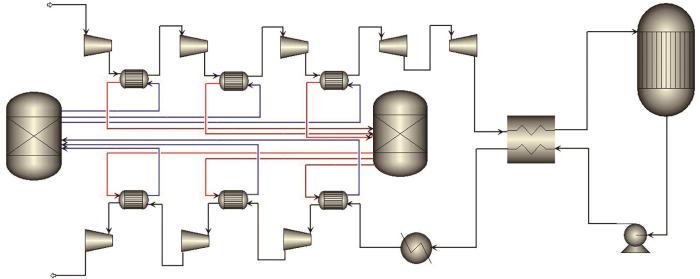
本文对非补燃液态空气储能系统进行物理建模,选取合适的物理模型对压缩机、换热器、透平、储罐及液泵等主要设备进行匹配设置,整个系统内工质流动沿着物理模型箭头方向依次流经各个设备。非补燃液态空气储能系统采用开式循环,物理模型如图2 所示。
图2
图2
非补燃液态空气储能系统物理模型
Fig. 2
Physical model of non-supplementary combustion liquid air energy storage system
4 关键参数敏感性分析
4.1 系统边界参数设置
为了分析热力系统关键参数对系统性能的影响,需对系统边界参数进行设置,如表1 所示。系统计算过程中不考虑管道压损以及温度损失。
4.2 压缩机级间温度
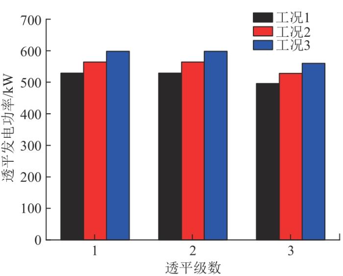
压缩机级间温度是一个直接影响压缩机组压缩效率及系统效率的关键参数。本文通过对比3种不同压缩机级间温度工况(见表2 ),研究了压缩机级间温度与压缩机消耗的电功率、透平发电功率、系统电-电转化效率及储能密度的关系,分别如图3 —5 所示。
由图3 可知,在储能过程中,工质质量流量不变,压缩机级数(第2、3、4级)相同情况下,压缩机级间温度越高,压缩机消耗的电功率越大,压缩机出口温度越高,级间回收的压缩热品质越高。第1级压缩由于入口空气温度相同,3种工况下压缩机消耗的电功率相同。在释能发电过程中,3种工况下透平入口压力相同,压缩机级间温度越高,透平入口空气温度越高,膨胀做功越大。这是由于压缩机入口温度越高,蓄热器回收的压缩阶段的高品质热量越大,透平入口空气温度越高,进而透平发电功率越大,如图4 所示。
图3
图3
压缩机级间温度与压缩机消耗的电功率关系
Fig. 3
Relationship between compressor interstage temperature and electric power consumed by compressor
图4
图4
压缩机级间温度与透平发电功率关系
Fig. 4
Relationship between compressor interstage temperature and turbine power generation
图5
图5
压缩机级间温度与电-电转化效率、储能密度关系
Fig. 5
Relationship between compressor interstage temperature and electric-electric conversion efficiency and energy storage density
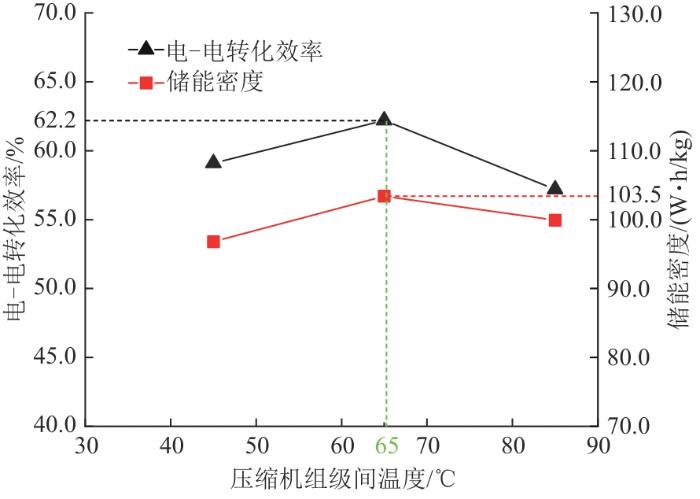
由图5 可知,当压缩机级间温度从45 ℃升高到65 ℃时,系统电-电转化效率提高,储能密度增大。当压缩机级间温度从65 ℃升高到85 ℃时,电-电转化效率及储能密度均呈下降趋势,其主要原因如下:压缩机级间温度升高,虽然透平发电功率增大,但同时压缩机消耗的电功率也增加,且增加的幅度大于透平有效发电功率,导致整个储能电-电转化效率降低。通过上述分析可知,选取压缩机级间温度65 ℃为最佳温度,此时,电-电转化效率为62.2%,储能密度为103.5 W⋅h/kg。
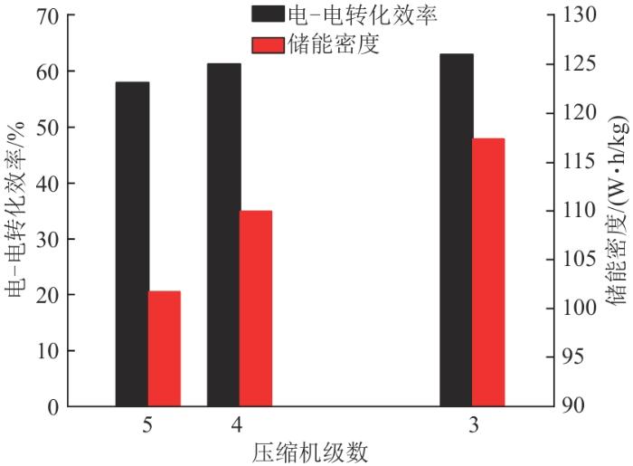
4.3 压缩机级数
压缩机级数是压缩机设备选型的关键参数,同时直接影响到压缩空气储能系统的性能参数。3种不同压缩机级数工况参数如表3 所示。
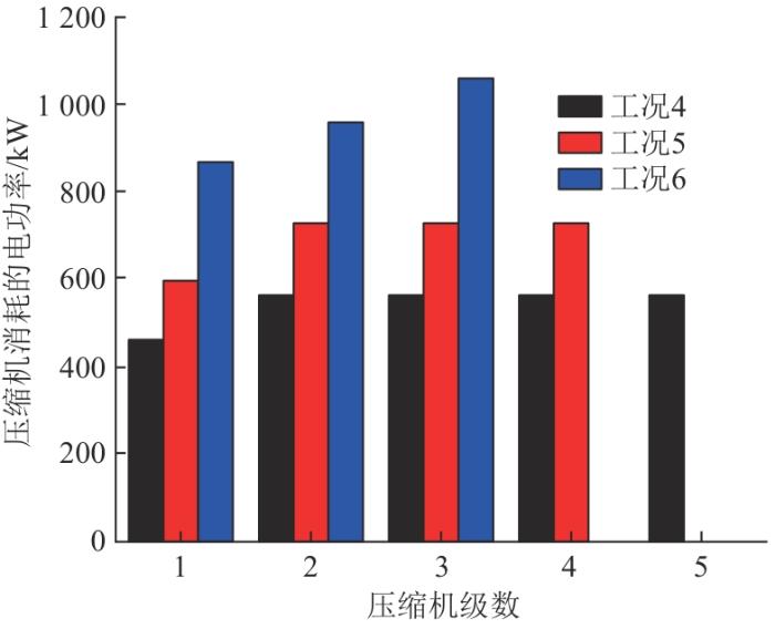
在压缩机级间温度为65 ℃,储气室空气压力、流量都相同的条件下,压缩机级数与压缩机消耗的电功率、透平发电功率、电-电转化效率、储能密度的关系分别如图6 —8 所示。
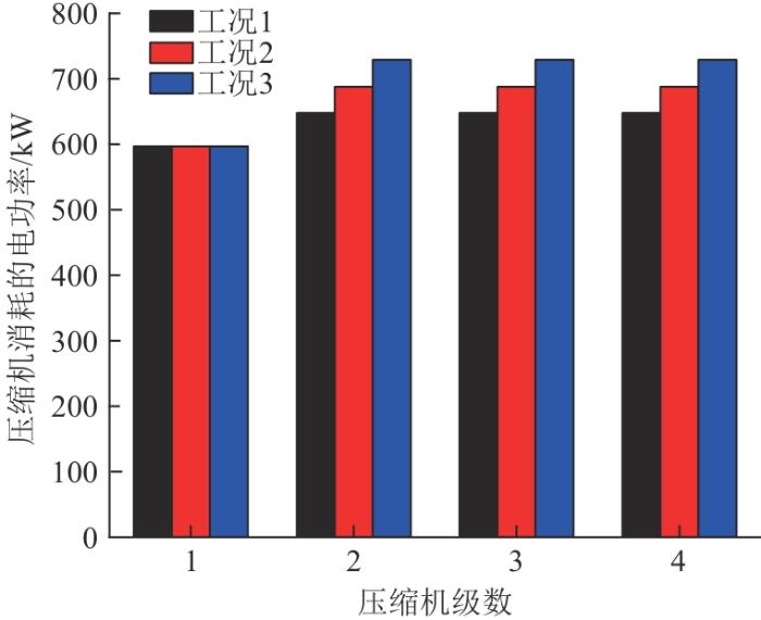
从图6 可以看出,随着压缩机级数减少,压缩机压缩阶段所消耗的电功率增大,这主要是由于在储能压力相同的情况下,压缩机级数越少,压缩机级间温度越高。
图6
图6
压缩机级数与压缩机消耗的电功率关系
Fig. 6
Relationship between number of compressor stages and electric power consumed by compressor
图7
图7
压缩机级数与透平发电功率的关系
Fig. 7
Relationship between number of compressor stages and turbine power generation
图8
图8
压缩机级数与电-电转化效率、储能密度的关系
Fig. 8
Relationship between number of compressor stages and electric-electric conversion efficiency and energy storage density
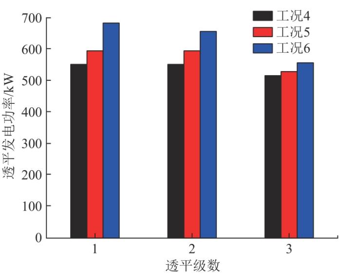
从图7 可以看出,随着压缩机级数的减少,透平发电功率增大,这是由于压缩机级数越少,压缩机级间压缩热品质越高,蓄热品质也越高,在透平发电过程中,其入口空气温度也相对越高,发电功率越大。在3种工况下,透平发电功率都呈现逐级降低趋势,这主要是由于在透平入口空气温度一定的情况下,透平入口空气压力呈现逐级降低趋势。
由图8 可见,随着压缩机级数减少,系统电-电转化效率提高,储能密度增大。就本文储能压力等级来说,若压缩机级数进一步减少,达到2级压缩或1级压缩,此时已超出压缩机目前的压缩能力,无法实现压缩功能[23 ] 。因此,当压缩机级数为3级时,系统电-电转化效率达到63.5%,储能密度达到119.5 W⋅h/kg,为最优工况。
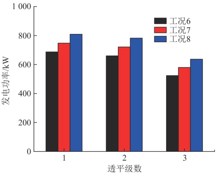
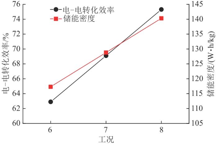
4.4 透平入口温度
透平入口温度是直接影响透平发电功率的关键参数,是系统电-电转化效率的重要影响因素,本文以绝热蓄热(工况6)为基础,对比外界给入热量为342 kW和689 kW两种工况,使得透平入口温度较基础工况分别提高了50 ℃和100 ℃,具体如表4 所示。
透平入口温度与发电功率、电-电转化效率、储能密度的关系分别如图9 、10 所示。从图9 可以看出,在压缩机级间温度、压缩机级数、质量流量均相同的条件下,透平入口温度越高,透平发电功率越大。在3种工况下,透平发电功率也呈现逐级降低趋势,与图7 所表现出的趋势相同。
图9
图9
透平入口温度与发电功率的关系
Fig. 9
Relationship between turbine inlet temperature and power generation
图10
图10
透平入口温度与电-电转化效率、储能密度的关系
Fig. 10
Relationship between turbine inlet air temperature and electric-electric conversion efficiency and energy storage density
从图10 可以看出,随着透平入口温度升高,电-电转化效率和储能密度均增大,增长趋势明显,说明透平入口温度对储能系统关键性能参数影响较大,未来为进一步提高该系统电-电转化效率,可充分利用周边余热、废热以及低谷电接入储能系统,以实现低品位能源的高效利用[24 ] 。
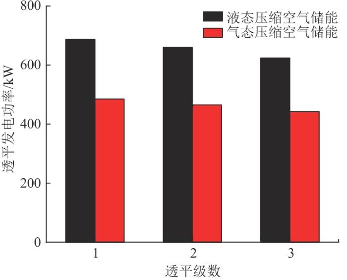
4.5 非补燃液态、气态压缩空气储能系统性能对比
为对比非补燃气、液态压缩空气储能系统的热力性能参数,设置边界参数如表5 所示。
在边界参数相同的情况下,常温、常压空气通过压缩机将空气压缩到相同压力及温度下,压缩机所消耗的电功率相同。2种压缩空气储能系统的透平发电功率对比如图11 所示。可以看出,若要储存相同容量的能量,非补燃液态系统的储能透平发电量明显高于非补燃气态系统。由于非补燃液态系统释放能量时,液态空气通过空气液态泵持续稳定输出压力,没有压力调节节流损失,透平发电功率较大。而非补燃气态储能系统在释能发电过程中,为了保证第一级透平入口空气压力稳定,储气室空气经过调节节流,造成能量损失,导致透平发电功率相对较小。
图11
图11
2种压缩空气储能系统的透平发电功率对比
Fig. 11
Comparison of turbine power generation of two compressed air energy storage systems
在电-电转化效率及储能密度方面,非补燃气态系统的电-电转化效率为53.5%,储能密度为25.4 W⋅h/kg,均低于非补燃液态系统(其电-电转化效率为63.5%,储能密度为119.5 W⋅h/kg)。
5 结论
提出一种非补燃液态压缩空气储能系统,可解决气态压缩空气储能能量储存的地理限制难题。借助仿真计算软件,构建了理论计算模型,对系统内关键参数进行了敏感性分析,并与非补燃气态压缩空气储能系统进行了对比。具体结论如下:
1)压缩机级间温度直接影响压缩功耗及透平发电,级间温度过低或过高都会制约储能系统电-电转化效率提升,因此选取合适的压缩机级间温度是保证系统性能参数的关键。
2)在一定的储气压力下,压缩机级数与压缩机耗功呈现正相关趋势,与透平发电功率呈现负相关趋势,因此选取合适的压缩机级数也是保证系统性能参数的关键。
3)在相同条件下,透平入口温度越高,发电功率越大,因此,为提升储能系统电-电转化效率,应尽可能提升透平入口温度。
4)在相同条件下,与非补燃气态压缩空气储能系统相比,非补燃液态压缩空气储能系统的电-电转化效率提高了10%,储能密度提高了3.7倍,储气室容积缩小了9/10。
参考文献
View Option
[2]
陈宏 ,贺悝 ,谭庄熙 ,等 考虑SOC均衡的储能电站一次调频协同控制方法
[J].电力科学与技术学报 ,2023 ,38 (6 ):105 -114 .
[本文引用: 1]
CHEN H HE L TAN Z X et al Coordinated control method of primary frequency regulation for energy storage power station considering SOC balance
[J].Journal of Electric Power Science and Technology ,2023 ,38 (6 ):105 -114 .
[本文引用: 1]
[3]
刘红 基于改进粒子群算法的储能调峰容量优化配置研究
[J].广东电力 ,2023 ,36 (1 ):68 -76 .
[本文引用: 1]
LIU H Research on optimal configuration of energy storage peak shaving capacity based on improved particle swarm optimization algorithm
[J].Guangdong Electric Power ,2023 ,36 (1 ):68 -76 .
[本文引用: 1]
[4]
吴盛军 ,李强 ,彭维馨 ,等 考虑平抑直流故障后功率波动的储能系统选址配置方法
[J].电力科学与技术学报 ,2023 ,38 (1 ):35 -42 .
[本文引用: 1]
WU S J LI Q PENG W X et al Site selection and configuration method of energy storage system for suppressing power fluctuation after DC fault
[J].Journal of Electric Power Science and Technology ,2023 ,
[本文引用: 1]
38 (1 ):35 -42 .
[本文引用: 1]
[6]
[本文引用: 1]
DE G R TIAN X Q WANG X L et al Research on multi-objective optimization model of the combined outward transmission dispatching of wind,solar,thermal-power and storage considering operation cost and emission
[J].Power System and Clean Energy ,2022 ,38 (6 ):121 -128 . doi:10.3969/j.issn.1674-3814.2022.06.016
[本文引用: 1]
[8]
韩晓娟 ,牟志国 ,魏梓轩 基于云模型的电化学储能工况适应性综合评估
[J].电力工程技术 ,2022 ,41 (4 ):213 -219 .
[本文引用: 1]
HAN X J MU Z G WEI Z X Comprehensive evaluation for the adaptability of electrochemical energy storage conditions based on cloud model
[J].Electric Power Engineering Technology ,2022 ,41 (4 ):213 -219 .
[本文引用: 1]
[9]
郑明辉 ,宋民航 ,王金星 “双碳”目标下燃煤机组转型目标与技术分析
[J].广东电力 ,2022 ,35 (7 ):14 -22 .
[本文引用: 1]
ZHENG M H SONG M H WANG J X Objective and technical analysis of coal-fired unit transformation under dual carbon goals
[J].Guangdong Electric Power ,2022 ,35 (7 ):14 -22 .
[本文引用: 1]
[12]
吴金龙 ,李峻 ,邢泰高 ,等 绝热压缩空气储能系统的热力性能与经济性分析
[J].热力发电 ,2024 ,53 (2 ):27 -36 .
[本文引用: 1]
WU J L LI J XING T G et al Thermodynamics and economic analysis of adiabatic compressed air energy storage system
[J].Thermal Power Generation ,2024 ,53 (2 ):27 -36 .
[本文引用: 1]
[13]
何青 ,贾明祥 ,康浩强 ,等 绝热压缩空气储能系统Aspen Plus软件自定义蓄热器模块设计及应用
[J].热力发电 ,2018 ,47 (2 ):114 -119 .
[本文引用: 1]
HE Q JIA M X KANG H Q et al Design and application of custom regenerator module in Aspen Plus for adiabatic compressed air energy storage system
[J].Thermal Power Generation ,2018 ,47 (2 ):114 -119 .
[本文引用: 1]
[14]
马兴民 深冷液化空气储能系统设计及分析
[D].北京 :华北电力大学 ,2021 .
[本文引用: 1]
MA X M Design and analysis of cryogenic liquefied air energy storage system
[D].Beijing :North China Electric Power University ,2021 .
[本文引用: 1]
[15]
苏要港 ,吴晓南 ,廖柏睿 ,等 耦合LNG冷能及ORC的新型液化空气储能系统分析
[J].储能科学与技术 ,2022 ,11 (6 ):1996 -2006 .
[本文引用: 1]
SU Y G WU X N LIAO B R et al Analysis of novel liquefied-air energy-storage system coupled with LNG cold energy and ORC
[J].Energy Storage Science and Technology ,2022 ,11 (6 ):1996 -2006 .
[本文引用: 1]
[16]
薛皓白 ,张新敬 ,陈海生 ,等 微型压缩空气储能系统释能过程分析
[J].工程热物理学报 ,2014 ,35 (10 ):1923 -1929 .
[本文引用: 5]
XUE H B ZHANG X J CHEN H S et al Analysis of energy release process of micro-compressed air energy storage systems
[J].Journal of Engineering Thermophysics ,2014 ,35 (10 ):1923 -1929 .
[本文引用: 5]
[17]
刘烨 ,魏高升 ,由文江 ,等 空气压缩系统深度节能技术
[J].发电技术 ,2018 ,39 (1 ):70 -76 .
[本文引用: 4]
LIU Y WEI G S YOU W J et al Deep energy saving technology in air compression system
[J].Power Generation Technology ,2018 ,39 (1 ):70 -76 .
[本文引用: 4]
[18]
李姚旺 ,苗世洪 ,尹斌鑫 ,等 含先进绝热压缩空气储能电站的电力系统实时调度模型
[J].电工技术学报 ,2019 ,34 (2 ):387 -397 .
[本文引用: 5]
LI Y W MIAO S H YIN B X et al Real-time dispatch model for power system with advanced adiabatic compressed air energy storage
[J].Transactions of China Electrotechnical Society ,2019 ,34 (2 ):387 -397 .
[本文引用: 5]
[19]
[本文引用: 1]
LI C C LI Y F ZHANG Y et al Novel steam constant-pressure pumped hydro with compressed air energy storage system and thermodynamic analysis
[J].Journal of Xi’an Jiaotong University ,2021 ,55 (6 ):84 -91 . doi:10.7652/xjtuxb202106011
[本文引用: 1]
[20]
姚尔人 ,王焕然 ,席光 ,等 等一种压缩空气储能与内燃机技术耦合的冷热电联产系统
[J].西安交通大学学报 ,2016 ,50 (1 ):22 -27 .
[本文引用: 1]
YAO E R WANG H R XI G et al A novel combined cooling heating and power system with coupled compressed air energy storage and combustion engine
[J].Journal of Xi’an Jiaotong University ,2016 ,50 (1 ):22 -27 .
[本文引用: 1]
[21]
[本文引用: 1]
WEN X K ZHAGN S H DENG T T et al A summary of large capacity power energy storage peak regulation and frequency adjustment performance
[J].Power Generation Technology ,2018 ,39 (6 ):487 -492 . doi:10.12096/j.2096-4528.pgt.18214
[本文引用: 1]
[22]
YAO E WANG H WANG L et al Thermo-economic optimization of a combined cooling,heating and power system based on small-scale compressed air energy storage
[J].Energy Conversion and Management ,2016 ,118 :377 -386 . doi:10.1016/j.enconman.2016.03.087
[本文引用: 1]
[23]
姜云涛 ,付林 ,胡鹏 ,等 电厂及工业废热利用新途径
[J].石油石化节能与减排 ,2011 (S1 ):29 -32 .
[本文引用: 1]
JIANG Y T FU L HU P et al New ways of waste heat utilization in power plants and industries
[J].Green Petroleum & Petrochemicals ,2011 (S1 ):29 -32 .
[本文引用: 1]
[24]
梅生伟 ,李瑞 ,陈来军 ,等 先进绝热压缩空气储能技术研究进展及展望
[J].中国电机工程学报 ,2018 ,38 (10 ):2893 -2907 .
[本文引用: 1]
MEI S W LI R CHEN L J et al An overview and outlook on advanced adiabatic compressed air energy storage technique
[J].Proceedings of the CSEE ,2018 ,38 (10 ):2893 -2907 .
[本文引用: 1]
考虑火电深度调峰的多类型储能经济性分析
1
2022
... 储能技术在削峰填谷、平滑负荷、提升负荷率的同时改善了部分火电机组的运行条件,使其从压荷状态变为稳定运行,减少了火电厂运行费用和发电成本[1 -2 ] .储能系统的投入使电网负荷趋于合理,提高了调峰火电机组效率,甚至可延缓或减少电源、电网建设,提高能源和资产利用率,从而有效改变电力系统建设模式[3 -4 ] .利用储能系统不仅能给传统火电机组带来可观的收益,还可使机组运行更平稳、安全、可靠,更适应电力系统需求的新模式,从而助力“双碳”目标的实现[5 -6 ] . ...
Economic analysis of multi-type energy storages considering the deep peak-regulation of thermal power units
1
2022
... 储能技术在削峰填谷、平滑负荷、提升负荷率的同时改善了部分火电机组的运行条件,使其从压荷状态变为稳定运行,减少了火电厂运行费用和发电成本[1 -2 ] .储能系统的投入使电网负荷趋于合理,提高了调峰火电机组效率,甚至可延缓或减少电源、电网建设,提高能源和资产利用率,从而有效改变电力系统建设模式[3 -4 ] .利用储能系统不仅能给传统火电机组带来可观的收益,还可使机组运行更平稳、安全、可靠,更适应电力系统需求的新模式,从而助力“双碳”目标的实现[5 -6 ] . ...
考虑SOC均衡的储能电站一次调频协同控制方法
1
2023
... 储能技术在削峰填谷、平滑负荷、提升负荷率的同时改善了部分火电机组的运行条件,使其从压荷状态变为稳定运行,减少了火电厂运行费用和发电成本[1 -2 ] .储能系统的投入使电网负荷趋于合理,提高了调峰火电机组效率,甚至可延缓或减少电源、电网建设,提高能源和资产利用率,从而有效改变电力系统建设模式[3 -4 ] .利用储能系统不仅能给传统火电机组带来可观的收益,还可使机组运行更平稳、安全、可靠,更适应电力系统需求的新模式,从而助力“双碳”目标的实现[5 -6 ] . ...
Coordinated control method of primary frequency regulation for energy storage power station considering SOC balance
1
2023
... 储能技术在削峰填谷、平滑负荷、提升负荷率的同时改善了部分火电机组的运行条件,使其从压荷状态变为稳定运行,减少了火电厂运行费用和发电成本[1 -2 ] .储能系统的投入使电网负荷趋于合理,提高了调峰火电机组效率,甚至可延缓或减少电源、电网建设,提高能源和资产利用率,从而有效改变电力系统建设模式[3 -4 ] .利用储能系统不仅能给传统火电机组带来可观的收益,还可使机组运行更平稳、安全、可靠,更适应电力系统需求的新模式,从而助力“双碳”目标的实现[5 -6 ] . ...
基于改进粒子群算法的储能调峰容量优化配置研究
1
2023
... 储能技术在削峰填谷、平滑负荷、提升负荷率的同时改善了部分火电机组的运行条件,使其从压荷状态变为稳定运行,减少了火电厂运行费用和发电成本[1 -2 ] .储能系统的投入使电网负荷趋于合理,提高了调峰火电机组效率,甚至可延缓或减少电源、电网建设,提高能源和资产利用率,从而有效改变电力系统建设模式[3 -4 ] .利用储能系统不仅能给传统火电机组带来可观的收益,还可使机组运行更平稳、安全、可靠,更适应电力系统需求的新模式,从而助力“双碳”目标的实现[5 -6 ] . ...
Research on optimal configuration of energy storage peak shaving capacity based on improved particle swarm optimization algorithm
1
2023
... 储能技术在削峰填谷、平滑负荷、提升负荷率的同时改善了部分火电机组的运行条件,使其从压荷状态变为稳定运行,减少了火电厂运行费用和发电成本[1 -2 ] .储能系统的投入使电网负荷趋于合理,提高了调峰火电机组效率,甚至可延缓或减少电源、电网建设,提高能源和资产利用率,从而有效改变电力系统建设模式[3 -4 ] .利用储能系统不仅能给传统火电机组带来可观的收益,还可使机组运行更平稳、安全、可靠,更适应电力系统需求的新模式,从而助力“双碳”目标的实现[5 -6 ] . ...
考虑平抑直流故障后功率波动的储能系统选址配置方法
1
2023
... 储能技术在削峰填谷、平滑负荷、提升负荷率的同时改善了部分火电机组的运行条件,使其从压荷状态变为稳定运行,减少了火电厂运行费用和发电成本[1 -2 ] .储能系统的投入使电网负荷趋于合理,提高了调峰火电机组效率,甚至可延缓或减少电源、电网建设,提高能源和资产利用率,从而有效改变电力系统建设模式[3 -4 ] .利用储能系统不仅能给传统火电机组带来可观的收益,还可使机组运行更平稳、安全、可靠,更适应电力系统需求的新模式,从而助力“双碳”目标的实现[5 -6 ] . ...
Site selection and configuration method of energy storage system for suppressing power fluctuation after DC fault
1
2023
... 储能技术在削峰填谷、平滑负荷、提升负荷率的同时改善了部分火电机组的运行条件,使其从压荷状态变为稳定运行,减少了火电厂运行费用和发电成本[1 -2 ] .储能系统的投入使电网负荷趋于合理,提高了调峰火电机组效率,甚至可延缓或减少电源、电网建设,提高能源和资产利用率,从而有效改变电力系统建设模式[3 -4 ] .利用储能系统不仅能给传统火电机组带来可观的收益,还可使机组运行更平稳、安全、可靠,更适应电力系统需求的新模式,从而助力“双碳”目标的实现[5 -6 ] . ...
1
... 储能技术在削峰填谷、平滑负荷、提升负荷率的同时改善了部分火电机组的运行条件,使其从压荷状态变为稳定运行,减少了火电厂运行费用和发电成本[1 -2 ] .储能系统的投入使电网负荷趋于合理,提高了调峰火电机组效率,甚至可延缓或减少电源、电网建设,提高能源和资产利用率,从而有效改变电力系统建设模式[3 -4 ] .利用储能系统不仅能给传统火电机组带来可观的收益,还可使机组运行更平稳、安全、可靠,更适应电力系统需求的新模式,从而助力“双碳”目标的实现[5 -6 ] . ...
碳达峰、碳中和背景下“十四五”时期发电技术趋势分析
1
2022
... 储能技术在削峰填谷、平滑负荷、提升负荷率的同时改善了部分火电机组的运行条件,使其从压荷状态变为稳定运行,减少了火电厂运行费用和发电成本[1 -2 ] .储能系统的投入使电网负荷趋于合理,提高了调峰火电机组效率,甚至可延缓或减少电源、电网建设,提高能源和资产利用率,从而有效改变电力系统建设模式[3 -4 ] .利用储能系统不仅能给传统火电机组带来可观的收益,还可使机组运行更平稳、安全、可靠,更适应电力系统需求的新模式,从而助力“双碳”目标的实现[5 -6 ] . ...
Analysis of power generation technology trend in 14th Five-Year Plan under the background of carbon peak and carbon neutrality
1
2022
... 储能技术在削峰填谷、平滑负荷、提升负荷率的同时改善了部分火电机组的运行条件,使其从压荷状态变为稳定运行,减少了火电厂运行费用和发电成本[1 -2 ] .储能系统的投入使电网负荷趋于合理,提高了调峰火电机组效率,甚至可延缓或减少电源、电网建设,提高能源和资产利用率,从而有效改变电力系统建设模式[3 -4 ] .利用储能系统不仅能给传统火电机组带来可观的收益,还可使机组运行更平稳、安全、可靠,更适应电力系统需求的新模式,从而助力“双碳”目标的实现[5 -6 ] . ...
1
... 储能技术在削峰填谷、平滑负荷、提升负荷率的同时改善了部分火电机组的运行条件,使其从压荷状态变为稳定运行,减少了火电厂运行费用和发电成本[1 -2 ] .储能系统的投入使电网负荷趋于合理,提高了调峰火电机组效率,甚至可延缓或减少电源、电网建设,提高能源和资产利用率,从而有效改变电力系统建设模式[3 -4 ] .利用储能系统不仅能给传统火电机组带来可观的收益,还可使机组运行更平稳、安全、可靠,更适应电力系统需求的新模式,从而助力“双碳”目标的实现[5 -6 ] . ...
计及运行成本与排放量的风光火储联合外送调度多目标优化模型研究
1
2022
... 储能技术在削峰填谷、平滑负荷、提升负荷率的同时改善了部分火电机组的运行条件,使其从压荷状态变为稳定运行,减少了火电厂运行费用和发电成本[1 -2 ] .储能系统的投入使电网负荷趋于合理,提高了调峰火电机组效率,甚至可延缓或减少电源、电网建设,提高能源和资产利用率,从而有效改变电力系统建设模式[3 -4 ] .利用储能系统不仅能给传统火电机组带来可观的收益,还可使机组运行更平稳、安全、可靠,更适应电力系统需求的新模式,从而助力“双碳”目标的实现[5 -6 ] . ...
Research on multi-objective optimization model of the combined outward transmission dispatching of wind,solar,thermal-power and storage considering operation cost and emission
1
2022
... 储能技术在削峰填谷、平滑负荷、提升负荷率的同时改善了部分火电机组的运行条件,使其从压荷状态变为稳定运行,减少了火电厂运行费用和发电成本[1 -2 ] .储能系统的投入使电网负荷趋于合理,提高了调峰火电机组效率,甚至可延缓或减少电源、电网建设,提高能源和资产利用率,从而有效改变电力系统建设模式[3 -4 ] .利用储能系统不仅能给传统火电机组带来可观的收益,还可使机组运行更平稳、安全、可靠,更适应电力系统需求的新模式,从而助力“双碳”目标的实现[5 -6 ] . ...
面向电力系统的液态金属电池储能技术
1
2022
... 目前市场上的电力储能技术种类繁多,但适用于火电机组大功率调峰的储能技术仅有熔盐储能[7 ] 、电化学储能[8 ] 及压缩空气储能[9 ] 3种.熔盐储能与火电机组耦合对原有火电机组热力系统影响较大,系统较为复杂,效率低.电化学储能容量偏小且存在安全风险.而压缩空气储能是可行性更高的一种大规模储能技术,其利用电能、热能及机械能相互转化,实现电能储存及释放,对火电机组影响较小,是一种安全可靠且可行的调峰储能技术[10 -11 ] . ...
Liquid metal battery energy storage technology for power system
1
2022
... 目前市场上的电力储能技术种类繁多,但适用于火电机组大功率调峰的储能技术仅有熔盐储能[7 ] 、电化学储能[8 ] 及压缩空气储能[9 ] 3种.熔盐储能与火电机组耦合对原有火电机组热力系统影响较大,系统较为复杂,效率低.电化学储能容量偏小且存在安全风险.而压缩空气储能是可行性更高的一种大规模储能技术,其利用电能、热能及机械能相互转化,实现电能储存及释放,对火电机组影响较小,是一种安全可靠且可行的调峰储能技术[10 -11 ] . ...
基于云模型的电化学储能工况适应性综合评估
1
2022
... 目前市场上的电力储能技术种类繁多,但适用于火电机组大功率调峰的储能技术仅有熔盐储能[7 ] 、电化学储能[8 ] 及压缩空气储能[9 ] 3种.熔盐储能与火电机组耦合对原有火电机组热力系统影响较大,系统较为复杂,效率低.电化学储能容量偏小且存在安全风险.而压缩空气储能是可行性更高的一种大规模储能技术,其利用电能、热能及机械能相互转化,实现电能储存及释放,对火电机组影响较小,是一种安全可靠且可行的调峰储能技术[10 -11 ] . ...
Comprehensive evaluation for the adaptability of electrochemical energy storage conditions based on cloud model
1
2022
... 目前市场上的电力储能技术种类繁多,但适用于火电机组大功率调峰的储能技术仅有熔盐储能[7 ] 、电化学储能[8 ] 及压缩空气储能[9 ] 3种.熔盐储能与火电机组耦合对原有火电机组热力系统影响较大,系统较为复杂,效率低.电化学储能容量偏小且存在安全风险.而压缩空气储能是可行性更高的一种大规模储能技术,其利用电能、热能及机械能相互转化,实现电能储存及释放,对火电机组影响较小,是一种安全可靠且可行的调峰储能技术[10 -11 ] . ...
“双碳”目标下燃煤机组转型目标与技术分析
1
2022
... 目前市场上的电力储能技术种类繁多,但适用于火电机组大功率调峰的储能技术仅有熔盐储能[7 ] 、电化学储能[8 ] 及压缩空气储能[9 ] 3种.熔盐储能与火电机组耦合对原有火电机组热力系统影响较大,系统较为复杂,效率低.电化学储能容量偏小且存在安全风险.而压缩空气储能是可行性更高的一种大规模储能技术,其利用电能、热能及机械能相互转化,实现电能储存及释放,对火电机组影响较小,是一种安全可靠且可行的调峰储能技术[10 -11 ] . ...
Objective and technical analysis of coal-fired unit transformation under dual carbon goals
1
2022
... 目前市场上的电力储能技术种类繁多,但适用于火电机组大功率调峰的储能技术仅有熔盐储能[7 ] 、电化学储能[8 ] 及压缩空气储能[9 ] 3种.熔盐储能与火电机组耦合对原有火电机组热力系统影响较大,系统较为复杂,效率低.电化学储能容量偏小且存在安全风险.而压缩空气储能是可行性更高的一种大规模储能技术,其利用电能、热能及机械能相互转化,实现电能储存及释放,对火电机组影响较小,是一种安全可靠且可行的调峰储能技术[10 -11 ] . ...
压缩空气储能技术原理
1
2013
... 目前市场上的电力储能技术种类繁多,但适用于火电机组大功率调峰的储能技术仅有熔盐储能[7 ] 、电化学储能[8 ] 及压缩空气储能[9 ] 3种.熔盐储能与火电机组耦合对原有火电机组热力系统影响较大,系统较为复杂,效率低.电化学储能容量偏小且存在安全风险.而压缩空气储能是可行性更高的一种大规模储能技术,其利用电能、热能及机械能相互转化,实现电能储存及释放,对火电机组影响较小,是一种安全可靠且可行的调峰储能技术[10 -11 ] . ...
Technical principle of compressed air energy storage system
1
2013
... 目前市场上的电力储能技术种类繁多,但适用于火电机组大功率调峰的储能技术仅有熔盐储能[7 ] 、电化学储能[8 ] 及压缩空气储能[9 ] 3种.熔盐储能与火电机组耦合对原有火电机组热力系统影响较大,系统较为复杂,效率低.电化学储能容量偏小且存在安全风险.而压缩空气储能是可行性更高的一种大规模储能技术,其利用电能、热能及机械能相互转化,实现电能储存及释放,对火电机组影响较小,是一种安全可靠且可行的调峰储能技术[10 -11 ] . ...
基于碳捕集与液态CO2 储能的综合能源系统优化调度
1
2023
... 目前市场上的电力储能技术种类繁多,但适用于火电机组大功率调峰的储能技术仅有熔盐储能[7 ] 、电化学储能[8 ] 及压缩空气储能[9 ] 3种.熔盐储能与火电机组耦合对原有火电机组热力系统影响较大,系统较为复杂,效率低.电化学储能容量偏小且存在安全风险.而压缩空气储能是可行性更高的一种大规模储能技术,其利用电能、热能及机械能相互转化,实现电能储存及释放,对火电机组影响较小,是一种安全可靠且可行的调峰储能技术[10 -11 ] . ...
Optimal scheduling of integrated energy systems based on carbon capture and liquid CO2 energy storage
1
2023
... 目前市场上的电力储能技术种类繁多,但适用于火电机组大功率调峰的储能技术仅有熔盐储能[7 ] 、电化学储能[8 ] 及压缩空气储能[9 ] 3种.熔盐储能与火电机组耦合对原有火电机组热力系统影响较大,系统较为复杂,效率低.电化学储能容量偏小且存在安全风险.而压缩空气储能是可行性更高的一种大规模储能技术,其利用电能、热能及机械能相互转化,实现电能储存及释放,对火电机组影响较小,是一种安全可靠且可行的调峰储能技术[10 -11 ] . ...
绝热压缩空气储能系统的热力性能与经济性分析
1
2024
... 目前非补燃气态压缩空气储能系统已趋于成熟,其采用多级压缩、常温高压气态存储、多级膨胀发电的工艺系统.通过示范项目发现,制约该储能系统的因素较多,如最佳压缩机级数、压缩级间温度、储气室容积、透平入口温度等,系统电-电转化效率及储能密度整体偏低[12 ] .液态压缩空气储能系统由于单位储能功率所需储气室体积小、效率高等优势而受到众多学者关注.何青等[13 ] 建立了液态空气储能系统的热力学模型和㶲分析模型,对系统内蓄热器热力特性及结构进行了研究分析.马兴民[14 ] 对深冷液化空气储能系统进行全面分析,提出了深冷液化空气储能系统设计的关键参数.苏要港等[15 ] 将液态压缩空气储能系统与液化天然气(liquefied natural gas,LNG)和有机朗肯循环(organic Rankine cycle,ORC)相结合,研究了多种ORC工质对系统能源利用率和㶲效率的影响. ...
Thermodynamics and economic analysis of adiabatic compressed air energy storage system
1
2024
... 目前非补燃气态压缩空气储能系统已趋于成熟,其采用多级压缩、常温高压气态存储、多级膨胀发电的工艺系统.通过示范项目发现,制约该储能系统的因素较多,如最佳压缩机级数、压缩级间温度、储气室容积、透平入口温度等,系统电-电转化效率及储能密度整体偏低[12 ] .液态压缩空气储能系统由于单位储能功率所需储气室体积小、效率高等优势而受到众多学者关注.何青等[13 ] 建立了液态空气储能系统的热力学模型和㶲分析模型,对系统内蓄热器热力特性及结构进行了研究分析.马兴民[14 ] 对深冷液化空气储能系统进行全面分析,提出了深冷液化空气储能系统设计的关键参数.苏要港等[15 ] 将液态压缩空气储能系统与液化天然气(liquefied natural gas,LNG)和有机朗肯循环(organic Rankine cycle,ORC)相结合,研究了多种ORC工质对系统能源利用率和㶲效率的影响. ...
绝热压缩空气储能系统Aspen Plus软件自定义蓄热器模块设计及应用
1
2018
... 目前非补燃气态压缩空气储能系统已趋于成熟,其采用多级压缩、常温高压气态存储、多级膨胀发电的工艺系统.通过示范项目发现,制约该储能系统的因素较多,如最佳压缩机级数、压缩级间温度、储气室容积、透平入口温度等,系统电-电转化效率及储能密度整体偏低[12 ] .液态压缩空气储能系统由于单位储能功率所需储气室体积小、效率高等优势而受到众多学者关注.何青等[13 ] 建立了液态空气储能系统的热力学模型和㶲分析模型,对系统内蓄热器热力特性及结构进行了研究分析.马兴民[14 ] 对深冷液化空气储能系统进行全面分析,提出了深冷液化空气储能系统设计的关键参数.苏要港等[15 ] 将液态压缩空气储能系统与液化天然气(liquefied natural gas,LNG)和有机朗肯循环(organic Rankine cycle,ORC)相结合,研究了多种ORC工质对系统能源利用率和㶲效率的影响. ...
Design and application of custom regenerator module in Aspen Plus for adiabatic compressed air energy storage system
1
2018
... 目前非补燃气态压缩空气储能系统已趋于成熟,其采用多级压缩、常温高压气态存储、多级膨胀发电的工艺系统.通过示范项目发现,制约该储能系统的因素较多,如最佳压缩机级数、压缩级间温度、储气室容积、透平入口温度等,系统电-电转化效率及储能密度整体偏低[12 ] .液态压缩空气储能系统由于单位储能功率所需储气室体积小、效率高等优势而受到众多学者关注.何青等[13 ] 建立了液态空气储能系统的热力学模型和㶲分析模型,对系统内蓄热器热力特性及结构进行了研究分析.马兴民[14 ] 对深冷液化空气储能系统进行全面分析,提出了深冷液化空气储能系统设计的关键参数.苏要港等[15 ] 将液态压缩空气储能系统与液化天然气(liquefied natural gas,LNG)和有机朗肯循环(organic Rankine cycle,ORC)相结合,研究了多种ORC工质对系统能源利用率和㶲效率的影响. ...
深冷液化空气储能系统设计及分析
1
2021
... 目前非补燃气态压缩空气储能系统已趋于成熟,其采用多级压缩、常温高压气态存储、多级膨胀发电的工艺系统.通过示范项目发现,制约该储能系统的因素较多,如最佳压缩机级数、压缩级间温度、储气室容积、透平入口温度等,系统电-电转化效率及储能密度整体偏低[12 ] .液态压缩空气储能系统由于单位储能功率所需储气室体积小、效率高等优势而受到众多学者关注.何青等[13 ] 建立了液态空气储能系统的热力学模型和㶲分析模型,对系统内蓄热器热力特性及结构进行了研究分析.马兴民[14 ] 对深冷液化空气储能系统进行全面分析,提出了深冷液化空气储能系统设计的关键参数.苏要港等[15 ] 将液态压缩空气储能系统与液化天然气(liquefied natural gas,LNG)和有机朗肯循环(organic Rankine cycle,ORC)相结合,研究了多种ORC工质对系统能源利用率和㶲效率的影响. ...
Design and analysis of cryogenic liquefied air energy storage system
1
2021
... 目前非补燃气态压缩空气储能系统已趋于成熟,其采用多级压缩、常温高压气态存储、多级膨胀发电的工艺系统.通过示范项目发现,制约该储能系统的因素较多,如最佳压缩机级数、压缩级间温度、储气室容积、透平入口温度等,系统电-电转化效率及储能密度整体偏低[12 ] .液态压缩空气储能系统由于单位储能功率所需储气室体积小、效率高等优势而受到众多学者关注.何青等[13 ] 建立了液态空气储能系统的热力学模型和㶲分析模型,对系统内蓄热器热力特性及结构进行了研究分析.马兴民[14 ] 对深冷液化空气储能系统进行全面分析,提出了深冷液化空气储能系统设计的关键参数.苏要港等[15 ] 将液态压缩空气储能系统与液化天然气(liquefied natural gas,LNG)和有机朗肯循环(organic Rankine cycle,ORC)相结合,研究了多种ORC工质对系统能源利用率和㶲效率的影响. ...
耦合LNG冷能及ORC的新型液化空气储能系统分析
1
2022
... 目前非补燃气态压缩空气储能系统已趋于成熟,其采用多级压缩、常温高压气态存储、多级膨胀发电的工艺系统.通过示范项目发现,制约该储能系统的因素较多,如最佳压缩机级数、压缩级间温度、储气室容积、透平入口温度等,系统电-电转化效率及储能密度整体偏低[12 ] .液态压缩空气储能系统由于单位储能功率所需储气室体积小、效率高等优势而受到众多学者关注.何青等[13 ] 建立了液态空气储能系统的热力学模型和㶲分析模型,对系统内蓄热器热力特性及结构进行了研究分析.马兴民[14 ] 对深冷液化空气储能系统进行全面分析,提出了深冷液化空气储能系统设计的关键参数.苏要港等[15 ] 将液态压缩空气储能系统与液化天然气(liquefied natural gas,LNG)和有机朗肯循环(organic Rankine cycle,ORC)相结合,研究了多种ORC工质对系统能源利用率和㶲效率的影响. ...
Analysis of novel liquefied-air energy-storage system coupled with LNG cold energy and ORC
1
2022
... 目前非补燃气态压缩空气储能系统已趋于成熟,其采用多级压缩、常温高压气态存储、多级膨胀发电的工艺系统.通过示范项目发现,制约该储能系统的因素较多,如最佳压缩机级数、压缩级间温度、储气室容积、透平入口温度等,系统电-电转化效率及储能密度整体偏低[12 ] .液态压缩空气储能系统由于单位储能功率所需储气室体积小、效率高等优势而受到众多学者关注.何青等[13 ] 建立了液态空气储能系统的热力学模型和㶲分析模型,对系统内蓄热器热力特性及结构进行了研究分析.马兴民[14 ] 对深冷液化空气储能系统进行全面分析,提出了深冷液化空气储能系统设计的关键参数.苏要港等[15 ] 将液态压缩空气储能系统与液化天然气(liquefied natural gas,LNG)和有机朗肯循环(organic Rankine cycle,ORC)相结合,研究了多种ORC工质对系统能源利用率和㶲效率的影响. ...
微型压缩空气储能系统释能过程分析
5
2014
... 第i 级压缩机出口压力[16 ] 表示为 ...
... 第i 级压缩机出口温度[16 ] 表示为 ...
... 第i 级压缩机进、出口温差[16 ] 表示为 ...
... 第i 级压缩机消耗功率[16 ] 表示为 ...
... 压缩机组总消耗电功率[16 ] 表示为 ...
Analysis of energy release process of micro-compressed air energy storage systems
5
2014
... 第i 级压缩机出口压力[16 ] 表示为 ...
... 第i 级压缩机出口温度[16 ] 表示为 ...
... 第i 级压缩机进、出口温差[16 ] 表示为 ...
... 第i 级压缩机消耗功率[16 ] 表示为 ...
... 压缩机组总消耗电功率[16 ] 表示为 ...
空气压缩系统深度节能技术
4
2018
... 第x 级空气侧换热器出口温度[17 ] 表示为 ...
... 压缩过程中冷却器换热量[17 ] 表示为 ...
... 透平膨胀过程中加热器换热量[17 ] 表示为 ...
... 换热器总吸热量或放热量[17 ] 表示为 ...
Deep energy saving technology in air compression system
4
2018
... 第x 级空气侧换热器出口温度[17 ] 表示为 ...
... 压缩过程中冷却器换热量[17 ] 表示为 ...
... 透平膨胀过程中加热器换热量[17 ] 表示为 ...
... 换热器总吸热量或放热量[17 ] 表示为 ...
含先进绝热压缩空气储能电站的电力系统实时调度模型
5
2019
... 第t 级透平出口压力[18 ] 表示为 ...
... 第t 级透平出口温度[18 ] 表示为 ...
... 透平进、出口温差[18 ] 表示为 ...
... 第t 级透平做功[18 ] 表示为 ...
... 透平机组总做功功率[18 ] 表示为 ...
Real-time dispatch model for power system with advanced adiabatic compressed air energy storage
5
2019
... 第t 级透平出口压力[18 ] 表示为 ...
... 第t 级透平出口温度[18 ] 表示为 ...
... 透平进、出口温差[18 ] 表示为 ...
... 第t 级透平做功[18 ] 表示为 ...
... 透平机组总做功功率[18 ] 表示为 ...
一种新型蒸汽恒压抽水压缩空气储能系统及其热力学分析
1
2021
... 液态空气泵近似于给水泵,升压过程近似为等温过程,给水泵消耗功[19 ] 为 ...
Novel steam constant-pressure pumped hydro with compressed air energy storage system and thermodynamic analysis
1
2021
... 液态空气泵近似于给水泵,升压过程近似为等温过程,给水泵消耗功[19 ] 为 ...
等一种压缩空气储能与内燃机技术耦合的冷热电联产系统
1
2016
... 储能容量是衡量储能系统的重要指标,其定义为压缩机组所消耗的电功率和液泵所消耗的电功率之和[20 ] ,即 ...
A novel combined cooling heating and power system with coupled compressed air energy storage and combustion engine
1
2016
... 储能容量是衡量储能系统的重要指标,其定义为压缩机组所消耗的电功率和液泵所消耗的电功率之和[20 ] ,即 ...
大容量电力储能调峰调频性能综述
1
2018
... 储能密度也是衡量储能系统的重要指标,其定义为单位体积储存物质的能量所释放的电能[21 ] : ...
A summary of large capacity power energy storage peak regulation and frequency adjustment performance
1
2018
... 储能密度也是衡量储能系统的重要指标,其定义为单位体积储存物质的能量所释放的电能[21 ] : ...
Thermo-economic optimization of a combined cooling,heating and power system based on small-scale compressed air energy storage
1
2016
... 本文采用电-电转化效率这一性能评价指标来衡量该系统的效率,表达式[22 ] 如下: ...
电厂及工业废热利用新途径
1
2011
... 由图8 可见,随着压缩机级数减少,系统电-电转化效率提高,储能密度增大.就本文储能压力等级来说,若压缩机级数进一步减少,达到2级压缩或1级压缩,此时已超出压缩机目前的压缩能力,无法实现压缩功能[23 ] .因此,当压缩机级数为3级时,系统电-电转化效率达到63.5%,储能密度达到119.5 W⋅h/kg,为最优工况. ...
New ways of waste heat utilization in power plants and industries
1
2011
... 由图8 可见,随着压缩机级数减少,系统电-电转化效率提高,储能密度增大.就本文储能压力等级来说,若压缩机级数进一步减少,达到2级压缩或1级压缩,此时已超出压缩机目前的压缩能力,无法实现压缩功能[23 ] .因此,当压缩机级数为3级时,系统电-电转化效率达到63.5%,储能密度达到119.5 W⋅h/kg,为最优工况. ...
先进绝热压缩空气储能技术研究进展及展望
1
2018
... 从图10 可以看出,随着透平入口温度升高,电-电转化效率和储能密度均增大,增长趋势明显,说明透平入口温度对储能系统关键性能参数影响较大,未来为进一步提高该系统电-电转化效率,可充分利用周边余热、废热以及低谷电接入储能系统,以实现低品位能源的高效利用[24 ] . ...
An overview and outlook on advanced adiabatic compressed air energy storage technique
1
2018
... 从图10 可以看出,随着透平入口温度升高,电-电转化效率和储能密度均增大,增长趋势明显,说明透平入口温度对储能系统关键性能参数影响较大,未来为进一步提高该系统电-电转化效率,可充分利用周边余热、废热以及低谷电接入储能系统,以实现低品位能源的高效利用[24 ] . ...


