


0 引言
有一种基于REBCO超导片切割形成的葫芦形双孔闭环超导片堆叠组装形成的闭环高温超导磁体可以实现磁通密度放大与累加效果。这种葫芦形双孔闭环超导片是按照哈氏合金、缓冲层、REBCO薄膜、银保护层、铜保护层的顺序加工而成,然后按照需要对外形进行切割。根据闭环超导磁通守恒的原理,这种新型结构的超导片可以实现在小圆孔中磁通密度放大的效果,因此不受超导带材生产技术的限制,将其堆叠成磁体单元后,多个单元组装形成的高温超导磁体最终可以实现磁通密度放大与累加的双重效果,从而实现高场输出[9]。
综上所述,需要考虑这种堆叠磁体在大电流、高磁场环境下运行的机械稳定性问题。当超导体处于磁场下时,电磁应力将作用在导体上,这时高电磁应力会影响超导体的性能。实际工作环境中,超导磁体通常处于电场和磁场中,因此分析这种条件下超导磁体的电磁性能和力学特性是十分必要的。高温超导磁体的实用化取决于其磁稳定性和机械性能。本文通过构建REBCO闭环超导葫芦形环片堆叠磁体的三维电磁力模型,分析其在场冷励磁方法下的电磁响应和应力应变分布情况,为高场磁体的实际应用提供参考。
1 模型建立
1.1 REBCO超导葫芦形环片结构
图1
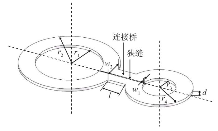
图1
REBCO超导葫芦形环片结构
Fig.1
Schematic view of REBCO superconducting gourd-shaped loop
表1 REBCO闭环超导葫芦形环片堆叠磁体参数
Tab. 1
| 参数 | 数值 |
|---|---|
| 大圆内半径r1/mm | 6 |
| 大圆外半径r2/mm | 9 |
| 小圆内半径r3/mm | 3 |
| 小圆外半径r4/mm | 6 |
| 狭缝宽w1/mm | 0.1 |
| 连接桥宽w2/mm | 4 |
| 连接桥长l/mm | 3 |
| 环片厚度d/mm | 0.1 |
| 磁体层数 | 10 |
这种葫芦形环片通过不同的堆叠组装成不同的磁通密度放大和磁通累加的磁体,根据适用场合灵活放置使用。图2给出了REBCO闭环超导葫芦形环片堆叠磁体示意图。基于闭环超导磁通守恒的原理,大圆环、小圆环流过相同的电流时,大圆环中产生磁通密度B,小圆环中会产生更大的磁通密度m×B(m>1)。
图2
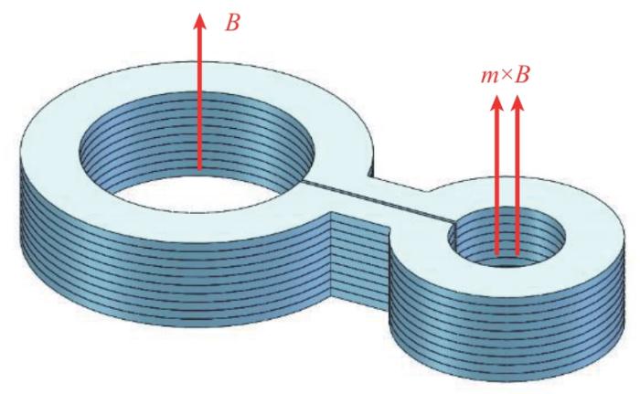
图2
REBCO闭环超导葫芦形环片堆叠磁体示意图
Fig. 2
Schematic diagram of REBCO closed-loop superconducting gourd-shaped loop stack magnets
1.2 应力应变计算有限元模型
搭建有限元模型的网格划分如图3所示,空气域将磁体、励磁线圈和铁芯包裹,磁体处在空气域中心的位置。为了能详细观察磁体的应力应变分布,在仿真中将REBCO涂层导体的超导层厚度扩大了100倍。为简化模型,只建模了REBCO的超导层来模拟磁体的受力情况,条件是保证超导材料不会失超。
图3
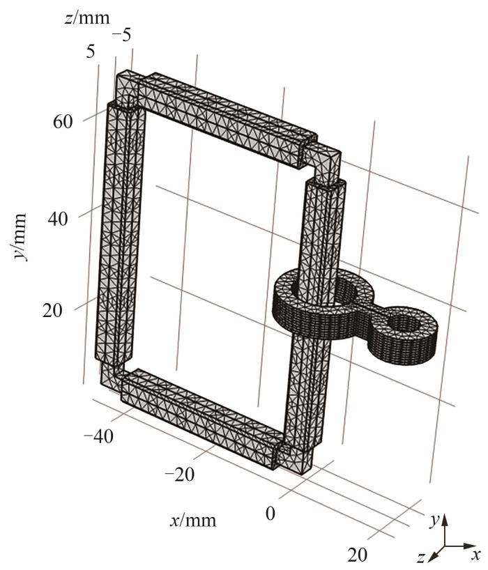
图3
REBCO闭环超导葫芦形环片堆叠磁体的网格划分
Fig. 3
Schematic diagram of mesh division of REBCO closed-loop superconducting gourd-shaped loop stack magnet
采用场冷励磁方法进行励磁,得到励磁电流时序图如图4所示。给励磁线圈通入电流以提供背景磁场,然后将整个磁体浸入液氮中,磁体进入超导态后,励磁线圈的电流缓慢降至0。
图4
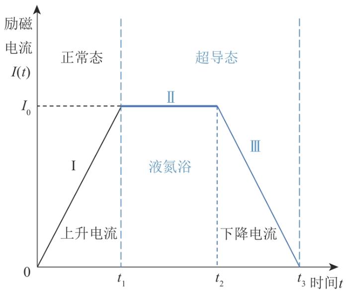
图4
场冷励磁方法下的励磁电流时序图
Fig. 4
Excitation current timing diagram under field cooling method
根据闭环超导体的磁通守恒,感应电流在大回路和小回路中产生并流动。独特的葫芦形结构使得小回路中心的磁通密度比大回路大[9]。
场冷励磁方法下REBCO闭环超导葫芦形环片堆叠磁体磁通密度放大原理示意图如图5所示。在初始正常态下,励磁线圈穿过葫芦形回路的大孔。在0—t1期间,电流I0通入励磁线圈,在铁芯内产生磁通密度B0。然后逐渐降低温度至77 K,葫芦形环路进入超导态。在t2—t3期间,将励磁线圈的电流缓慢减小至0,在葫芦形回路中产生感应电流I1,以维持磁通守恒。
图5
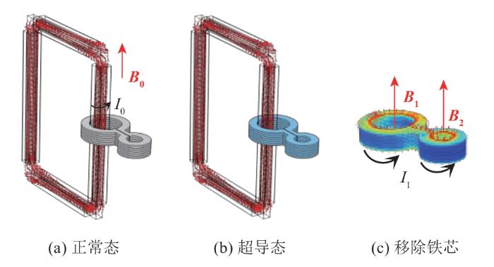
图5
场冷励磁方法下REBCO闭环超导葫芦形环片堆叠磁体磁通密度放大原理
Fig. 5
Schematic diagram of magnetic flux amplification of REBCO closed-loop superconducting gourd-shaped loop stack magnet under field cooling method
1.3 基本方程
1.3.1 电磁场仿真模块的建立
计算超导电磁场的麦克斯韦方程组为
超导的电磁本构方程为
式中:
由式(
式中
写入有限元软件的偏微分方程模块中为
式中:
超导区域的电阻率采用非线性的幂指数函数(E-J定律)来描述超导体的电压电流特性,E-J定律可以得到区别于正常金属线性电阻率的超导体等效电阻,即
式中:
式中:
1.3.2 固体力学模块的建立
假设环片的力学响应为准静态,因此不考虑惯性项的平衡方程为
式中:
运用弹性力学基本方程来处理电磁应力的问题,平衡方程得到应力分量和单位体积电磁力分量的关系式[20]如下:
式中:
微元体线段上的应变分量与位移分量之间的关系如下:
式中:
应变分量与应力分量之间的物理关系式如下:
式中:
2 仿真结果与分析
2.1 磁体的电流密度分布、磁场分布
励磁结束后,葫芦形回路中产生感应电流I1,以维持磁通守恒。励磁完成后葫芦形堆叠磁体的电流密度分布云图如图6所示。
图6
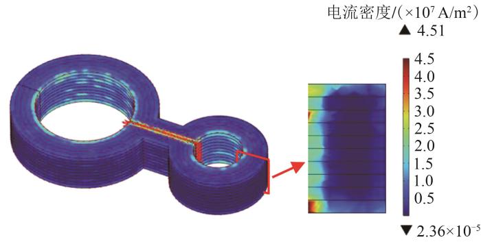
图6
励磁完成后葫芦形堆叠磁体的电流密度分布云图
Fig. 6
Current density distribution cloud diagram of gourd-shaped stacked magnets after excitation
图7
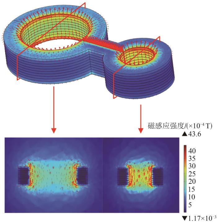
图7
励磁完成后葫芦形堆叠磁体的磁场分布云图
Fig. 7
Magnetic field distribution cloud diagram of gourd-shaped stacked magnets after excitation
图8
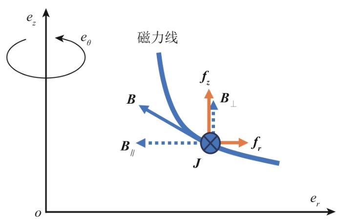
图8
柱坐标下求解单位体积电磁力示意图
Fig. 8
Schematic diagram of solving unit volume electromagnetic force in cylindrical coordinates
图9
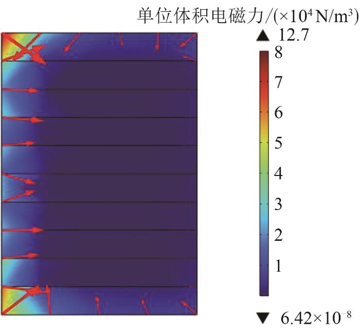
图9
励磁完成后葫芦形堆叠磁体沿径向的单位体积电磁力分布云图
Fig. 9
Cloud diagram of the unit volume electromagnetic force distribution along the radial direction of the gourd-shaped stacked magnet after excitation
以葫芦形堆叠磁体的底部为第1层,依次编号为第2,3,…,10层。第1层和第10层的单位体积电磁力的最大值最大,高达2 664 N/m3,两端向中部逐渐减小,第5、6层单位体积电磁力的最大值最小,低至767.96 N/m3。
第2层相对于第1层的最大单位体积电磁力降低了59.55%。这是因为第1层葫芦形环片具有更大的磁场分布和电流密度分布。因此,在这种葫芦形堆叠磁体中,顶部和底部内侧有力的集中。每一层的最大单位体积电磁力大小如图10所示。
图10
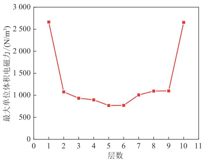
图10
每一层的最大单位体积电磁力大小
Fig. 10
The maximum unit volume electromagnetic force of each layer
2.2 磁体的应力应变分析
求得磁体的单位体积电磁力后,由平衡方程、几何方程和本构方程得到葫芦形堆叠磁体的正应力和切应力分布,如图11所示。
图11
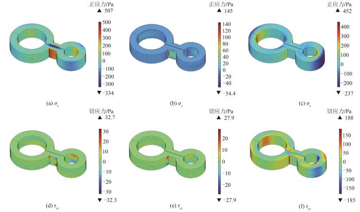
图11
葫芦形堆叠磁体的正应力、切应力分布云图
Fig. 11
Normal stress and shear stress distribution cloud diagram of gourd-shaped stacked magnets
总体来看,应力在磁体的连接桥部位以及圆孔与桥的交点处(弯曲较多的区域)明显较大,这些区域应力较集中,是可能失超的潜在风险点。2个圆环的应力分布集中在圆环的内径和两端,相对桥区域较均匀。
定量来看,x方向正应力和z方向正应力较大,最大值分别高达507 Pa和452 Pa,这是由于在这2个方向上的体载荷相对较重,沿y方向应力分量较小,只有145 Pa。zx平面的剪切应力较大,最大值有188 Pa,表明环片在zx平面上经历了较大的扭转作用力,xy和yz平面的剪切应力较小,因此磁体在这2个方向上扭转的程度较小。
为了能明显观察到REBCO闭环超导葫芦形环片堆叠磁体的扭转和位移,将其位移放大了100倍,得到沿x、y、z方向的位移如图12所示。
图12
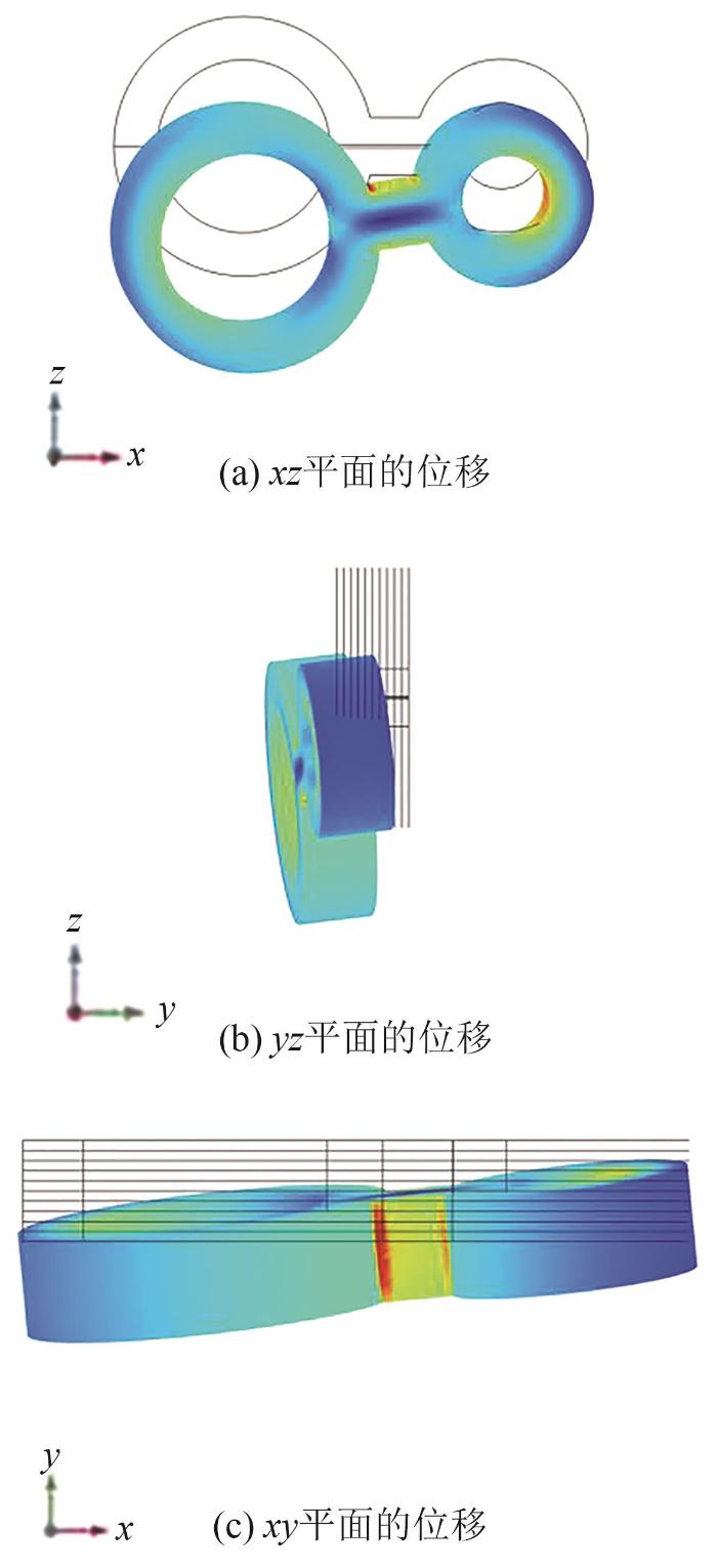
图12
葫芦形堆叠磁体的位移变化图
Fig. 12
Displacement variation diagram of gourd-shaped stacked magnets
由图12可以看到,大圆圆环相对于小圆圆环沿z方向的位移更大;葫芦形堆叠磁体整体以桥为轴,相对于zx平面扭转程度较大,且环片整体沿z方向下移,沿y方向下有一定位移,与它受到的应力产生的效果一致。因此,在实际使用中要考虑应力应变因素对磁体产生的影响。
3 结论
给出了计算REBCO闭环超导葫芦形环片堆叠磁体的电磁场分布的H方法控制方程及其有限元离散格式。基于该方法,构建了REBCO闭环超导葫芦形环片堆叠磁体的三维电磁力模型,该模型通过场冷励磁方法对磁体励磁,得到了电流密度分布、磁场分布和单位体积电磁力分布,其各个方向的应力张量和应变张量,以及受电磁应力后磁体的位移变形情况。得到以下结论:
1)REBCO闭环超导葫芦形环片堆叠磁体的单位体积电磁力由圆环的内径向外径逐渐减小,最大单位体积电磁力在堆叠磁体的两端层数较高,而中间层数则显著降低,最大单位体积电磁力随层数变化的趋势呈现明显的“U”型分布特征。
2)REBCO闭环超导葫芦形环片堆叠磁体的应力在磁体的连接桥部位以及圆孔与桥的交点处(弯曲较多的区域)明显较大,这些区域应力较集中,受力情况差,易发生形变,是可能失超的潜在风险处。
参考文献
A field-shaking system to reduce the screening-current-induced field in the 800-MHz HTS insert of the MIT 1.3-GHz LTS/HTS NMR magnet:a small-model study
[J].
Thermal loss analysis,design,and test of a novel HTS magnet system for the double-stator field-modulation HTS electrical machine
[J].
High-temperature superconducting magnets for NMR and MRI:R&D activities at the MIT francis bitter magnet laboratory
[J].
Persistent current joints between technological superconductors
[J].
Electrical properties of cold-pressing welded NbTi persistent joints
[J].
Superconducting joint and persistent current switch for a 7-T animal MRI magnet
[J].
Design and fabrication of permanent mode magnet by using coated conductor
[J].
A stack of YBCO annuli,thin plate and bulk,for micro-NMR spectroscopy
[J].
A gourd-shape HTS plate-loop with flux density amplification function
[J].
Evaluation of the electromechanical properties in GdBCO coated conductor tapes under low cyclic loading and bending
[J].
Delamination strength of YBCO coated conductors under transverse tensile stress
[J].
Thermal contraction of superconducting magnet materials
[J].
The optimal design of 600 kJ SMES magnet based on stress and magnetic field analysis
[J].
Degradation of a REBCO coil due to cleavage and peeling originating from an electromagnetic force
[J].
Screening current rotation effects:SCIF and strain in REBCO magnets
[J].
Screening-current-induced mechanical strains in REBCO insert coils
[J].
Screening current induced magnetic field and stress in ultra-high-field magnets using REBCO coated conductors
[J].
Finite-element modelling of no-insulation HTS coils using rotated anisotropic resistivity
[J].
H-formulation for simulating levitation forces acting on HTS bulks and stacks of 2G coated conductors
[J].
